


8 Controller Operation
This section discusses in detail how to operate the furnace temperature control
-
ler using the front control panel. By using the front panel key-switches and
LED display the user may monitor the well temperature, adjust the set-point
temperature in degrees C or F, monitor the heater output power, adjust the con
-
troller proportional band, and program the probe calibration parameters, operat
-
ing parameters, serial interface configuration, and controller calibration
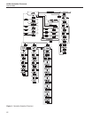
parameters. Operation of the functions and parameters are shown in the
flowchart in Figure 4 on page 22. This chart may be copied for reference.
In the following discussion a button with the word SET, UP, DOWN, or EXIT
inside indicates the panel button while the dotted box indicates the display
reading. Explanation of the button or display reading are to the right of each
button or display value.
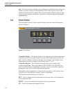
8.1 Well Temperature
The digital LED display on the front panel allows direct viewing of the actual
well temperature. This temperature value is what is normally shown on the dis-
play. The units, C or F, of the temperature value are displayed at the right. For
example,
962.3 C Well temperature in degrees Celsius
The temperature displayed function may be accessed from any other function
by pressing the “EXIT” button.
8.2 Temperature Set-point
The temperature set-point can be set to any value within the range and resolu
-
tion as given in the specifications. Be careful not to exceed the safe upper tem
-
perature limit of any device inserted into the well.
Setting the temperature involves two steps: (1) select the set-point memory and
(2) adjust the set-point value.
8.2.1 Programmable Set-points
The controller stores 8 set-point temperatures in memory. The set-points can be
quickly recalled to conveniently set the calibrator to a previously programmed
temperature set-point.
To set the temperature one must first select the set-point memory. This function
is accessed from the temperature display function by pressing “SET”. The
number of the set-point memory currently being used is shown at the left on the
display followed by the current set-point value.
21
8 Controller Operation
Well Temperature