


6 Parts and Controls
The user should become familiar with the furnace back panel, front panel, and
constant temperature block assembly.
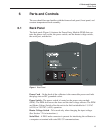
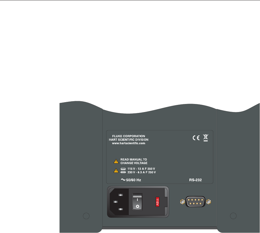
6.1 Back Panel
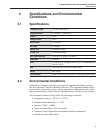
The back panel (Figure 1) features the Power Entry Module (PEM) that con
-
tains the power cord socket, the power switch, and the heater voltage switch,
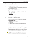
the serial port, and the fan.
Power Cord - On the back of the calibrator is the removable power cord inlet
that plugs into an IEC grounded socket.
Power Switch - The power switch is located on the power entry module
(PEM). The PEM also houses the fuses and the dual voltage selector. The PEM
and Heater Voltage Switch allow the unit to be field switchable for 115 VAC
(±10%) or 230 VAC (±10%) operation.
Heater Voltage Switch - To be used only when changing the input voltage.
(See Section 7.2 for instructions.)
Serial Port - A DB-9 male connector is present for interfacing the calibrator to
a computer or terminal with serial RS-232 communications.
15
6 Parts and Controls
Back Panel
Figure 1 Back Panel