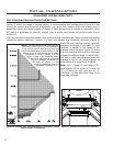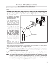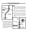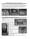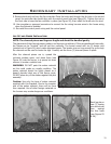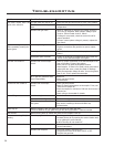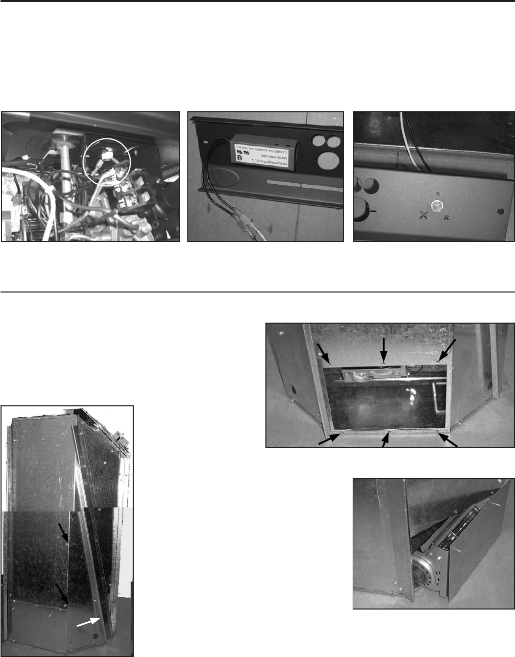
Figure 49. Install Fan Controller. Figure 50. Install Fan
Controller Nut.
Secondary Installation
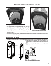
5. Slide the fan temp sensor in place under the holding tabs above the SIT valve (see Figure 48).
6. Remove knob and nut from the fan controller. Place the knob stud through the fan hole in the control
panel, the controller tab should align with the control panel hole (see Figure 49). Tighten the nut on
the front side to keep the fan controller in place (see Figure 50), then install the knob onto the stud.
7. Use marrettes or approved connectors to connect the fan harness wires to the house wiring.
8. Re-install the control panel wiring and control panel.
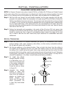
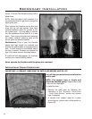
Figure 52: Move Back
Stand-Off.
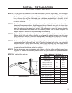
Figure 53: Installing Fan Through
the Back.
OPTIONAL FAN KIT INSTALLATION THROUGH BACK OF RETREAT:
1. Use a at head screwdriver or a ” socket to remove the six (6) screws securing the back cover (see
Figure 51).
Figure 51: Removing Back Plate From Retreat.
Figure 48: Installing Temperature
Sensor.
2. Remove the two (2) bottom screws securing the
stand-off (see Figure 52) and swing it out of the
way.
3. Install the two (2) grommets; place a 8-32 x ”
bolt through each grommet, then screw the bolt
to the back cover
using a ” socket.
4. Ensure the wiring
harness is attached
to the fan then hook
the two (2) slots on the fan box over
the grommets installed in the last
step.
5. Slide the fan and wiring harness
assembly into the hole in the back
of the Retreat, motor side rst (see
Figure 53).
6. Re-install the back cover and the
stand-off screws.
7. Remove the two (2) screws holding
the control panel in place. Disconnect
the sparker and rocker switch wires,
and remove the panel.
8. Slide the fan temp sensor in place under the holding tabs above the SIT
valve (see Figure 48).
32


