


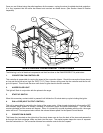
SLIDER/DAMPER INSTALLATION INSTRUCTIONS
This is used to regulate the airflow through the pellet
stove.
A Qualified Service Technician or Installer should set the
Slider Damper.
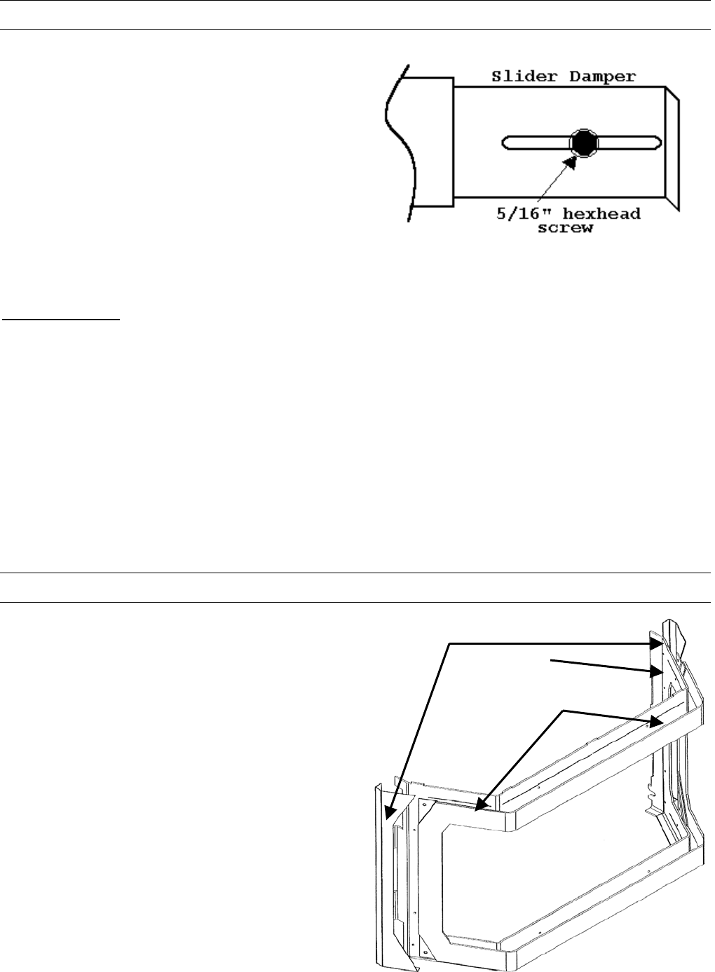
The Slider Damper is pre set from the factory. The slider
damper will be set and held in place with a 5/16” hex head
screw. This screw will be tightened in the middle of the
slot located in the slider damper plate.
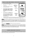
The slider damper is located behind the left side panel.
To open the left side panel, undo the one screw located in
the upper front corner of the cabinet side
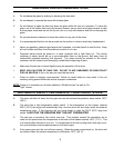
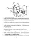
The combustion exhaust blower is a variable speed blower controlled by the heat output knob,(Dial a Fire). This
blower will decrease the vacuum pressure inside the stove and as the heat output knob is turned up. The vacuum
pressure inside the firebox will increase as the combustion exhaust blower increases in speed.
SPECIAL NOTES:
Pellet quality is a major factor in how the Pellet stove will operate. If the Pellets have a high moisture content or
ash content the fire will be less efficient and has a higher possibility of the fire building up and creating clinkers.
(hard ash build-up)
If the fire should happen to go out and the Dial A Fire has been set on the lowest setting, the Slider Damper
should be pushed in slightly decreasing the air in the firebox.
If after long periods of burning the fire builds up and over flows the burn pot or there is a build up of clinkers This
would be a sign that the pellet quality is poor and the slider damper must be pulled out to compensate.
Pulling the slider damper out gives the fire more air.
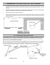
The easiest way to make sure that an efficient flame is achieved is to see the characteristics of the fire.
• A tall and lazy flame with dark orange tips requires more air – Open slider / damper up.
• A short and brisk flame, like a blowtorch, has too much air – Close slider / damper down.
• If the flame is in the middle of these two characteristics with a bright yellow/orange, active flame then the air is
set for proper operation.
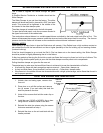
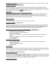
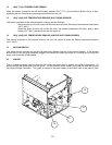
CLIP ON DOOR INSTALLATION
1. Unlatch door and swing open, remove door
form unit.
2. Place door on a soft flat surface and remove
the (4) screws (2 on each side) that hold the
side trim pieces to the door.
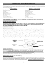
Side trim
pieces
2 screws per
side
Inner door
Clip on door (GOLD
or NICKEL)
3. Undo all four screws that hold the outer clip on
the door.
4. Install the new ( GOLD or NICKEL) clip on door
using the four screws to fasten to the door.
5. Reinstall the side trim pieces using the screws
that were removed from step 1.
6. Reinstall the door on the unit and latch with the
handle provided.
7