


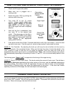
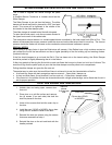
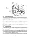

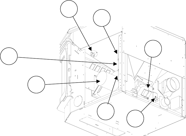
6. EXHAUST/COMBUSTION BLOWER
8
11
14
10
7
9
5
This variable speed fan (mounted on the left side of the stove) is responsible for drawing the outside fresh air into
the combustion chamber for burning. The hot air then continues to be drawn over the heat exchanger tubes and
into the exhaust channel. It is then pushed out through the exhaust system. A motor speed controller tied in with
the Dial-A-Fire controls the speed of the blower.
7. AUGER MOTOR AND AUGER
The 1 rpm auger motor is responsible for turning the auger, which in turn transports pellets to be dropped into the
burn pot. The auger motor’s control is handled by the timing control module and Dial-A-Fire.
8. EXHAUST/COMBUSTION PHASE CONTROLLER (BLOWER SPEED CONTROL MODULE)
The phase controller supplies an adjustable voltage to the combustion blower. The voltage controls the blower’s
speed. The module is controlled by a potentiometer in the Dial a Fire. As the feed rate is increased, the blower’s
speed is increased proportionally.
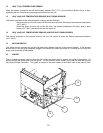
9. TIMING CONTROL MODULE
The timing control module is mounted in the middle, on the right rear pillar of the stove. The module controls the
switching of power to the auger motor. The module’s switching duty cycle is controlled by the dial-a-fire.
10. START-UP TIMER
This 15-minute one-shot timer, bypasses the 120°F (49°C) temperature sensor allowing the stove to operate
when cold. The timing cycle is initiated by pressing the start-up switch. The 15-minute timer is located right
under the timing control module on the right side pillar. This unit is also responsible for initiating the ignition cycle.
11. 200°F (93°C) MANUAL RESET TEMPERATURE SENSOR
This sensor (located on the right side firewall) has a red push button located in its center. This is a safety device.
In the event that the convection blower fails, this sensor will overheat and shut off power to the auger motor.
11