


21
Initial Installation
QUALIFIED INSTALLERS ONLY
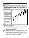
STEP 5. Cut hole in the roof centered on the small hole placed in the roof from Step 2. The hole should
be of sufcient size to meet minimum requirements for Clearance to Combustibles, as specied.
Continue to assemble lengths of pipe and elbows necessary to reach from the ceiling support
box up through the roof line. Galvanized pipe and elbows may be utilized in the attic, as well
as above the roof line. The galvanized nish is desirable above the roof line, due to the higher
corrosion resistance.
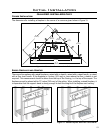
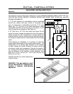
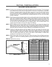
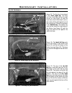
STEP 6. Once the pipe sections have been joined, and run up through the hole in the roof, slip an elbow
strap over the exposed sections, bend the support straps outwards, and push the elbow strap
down to the roof level, as shown in Figure 23. Tighten the clamp around the pipe section. Use
a level to make sure the pipe is truly vertical. With roong nails, secure the support straps to
the roof. Seal the nails holes heads with non-hardening mastic. Trim the excess length of the
support straps that extend out beyond the edge of the ashing.
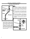
STEP 7. Slip the ashing over the pipe section protruding through the roof. Secure the base of the
ashing to the roof with roong nails. Use a non-hardening sealant between the uphill edge
of the ashing and the roof. Insure the roong material overlaps the top edge of the ashing.
Verify that you have at least the minimum clearance to combustibles at the roof line.
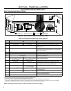
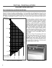
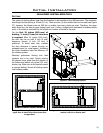
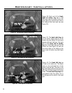
STEP 8. Continue to add pipe sections until the height of the vent cap meets the minimum code
requirements. Refer to Figure 24 and Table 3. Note that for steep roof pitches, the vent height
must be increased. In high wind conditions, nearby trees, adjoining roof lines, steep pitched
roofs, and other similar factors can result in poor draft, or down drafting. In these cases,
increasing the vent height may solve the problem.
STEP 9. Slip the storm collar over the pipe, and push it down to the top of the roof ashing as shown
in Figure 23. Use the non-hardening sealant around the joint between the pipe and the storm
collar.
STEP 10. Twist-lock the vent cap.
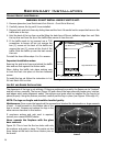
H
Dimension ‘H’ obtained
from table below.
Table 3: Minimum ‘H’ for Figure 24
Roof Pitch Minimum Height (H)
Feet Meters
Flat to 7/8 1 0.3
Over 7/12 to 8/12 1.5 0.46
Over 8/12 to 9/12 2 0.61
Over 9/12 to 10/12 2.5 0.76
Over 10/12 to 11/12 3.25 0.99
Over 11/12 to 12/12 4 1.22
Over 12/12 to 14/12 5 1.52
Over 14/12 to 16/12 6 1.83
Over 16/12 to 18/12 7 2.13
Over 18/12 to 20/12 7.5 2.29
Over 20/12 to 21/12 8 2.44
Figure 24: Height of Vertical Termination;
Reference Table 3.