


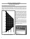
Note: 0,0 represents
a 90° bend directly
off the top of the unit.
5
4
3
2
1
0' (0m)
0' (0m)
5' (1.52m)
10' (3.05m)
4' (1.22m)
15' (4.57m)
10' (3.06m)
20' (6.11m)
30' (9.17m)
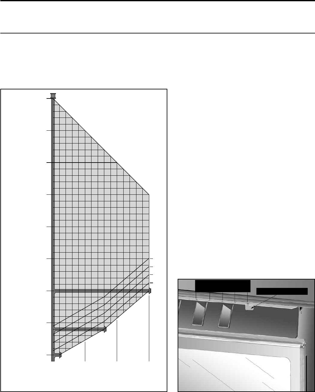
Vent Restrict or Configuration
40' (12.19m)
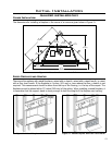
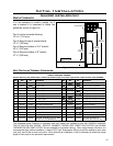
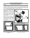
Figure 20. Possible Vent Congurations
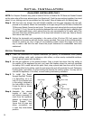
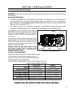
Vent Restrictor Positions
5 4 3 2 1
Vent Restrictor Handle
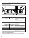
Figure 21. Possible Vent Restrictor Positions
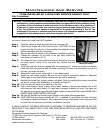
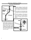
Initial Installation
QUALIFIED INSTALLERS ONLY
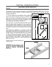
VENT CONFIGURATIONS AND RESTRICTOR SETTINGS:
Figures 20 shows the range of venting options, it shows possible vent congurations if the unit is top
vented, for vertical and horizontal terminations, any layout that remains within the shaded area is
acceptable. Having the fewest number of elbows is ideal, as they tend to disrupt air movement. Using
45˚ elbows is preferable to using 90˚ elbows. Also, a shorter vent system will perform better than a
longer one.
The vent restrictor controls the amount of air
moving through the vent pipe. Longer vertical
vent lengths necessitate greater restriction;
position 1 is open and position 5 is maximum
restriction. Figure 20 shows the vent restrictor
settings required, relative to the length of vent
pipe. The vent restrictor is located on the right
side of the replace, above the glass. Figure
21 shows the vent restrictor handle and the
holes that indicate the different levels. To avoid
injury, it is best to make this adjustment when
the replace is cool or use welder’s gloves or
oven mitts.
Note: 0,0 in Figure 20 represents a 90˚ bend
directly off the outlet of the unit, 46” (1169 mm)
from oor. This is for all horizontal instances
except when using Selkirk and having less
than a 4 feet (1.22 m) rise and 8 feet (2.44 m)
horizontal offset. In this case, a 1 foot rise must
be added below the 90˚ bend.
18