


12
Initial Installation
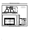
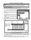
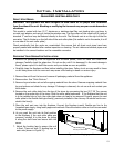
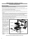
Check draft with a match
or smoke in a " (6 mm)
tube located here.
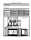
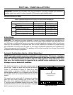
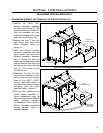
MINIMUM FIREPLACE SIZE:
Description of Fireplace Dimension Direct Vent B-Vent
Width
At Back 23 ” (591 mm) 23 ” (591 mm)
At Front 35” (889 mm) 35” (889 mm)
Height
With Surround Only 23 ” (603 mm) 23 ” (603 mm)
With Surround with Trim 23” (584 mm) 23” (584 mm)
Depth
With Surround Only 18” (457 mm) 19” (483 mm)
With Surround with Trim 16 ” (419 mm) 17 ” (445 mm)
B-VENT MODEL:
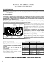
WARNING: This appliance has been designed to operate by drawing combustion air and dilution air
from the room. It is also designed to draw room air for proper heat circulation from the sides of the
unit. Blocking or modifying the louvers in any way can create hazardous situations, either through poor
venting or by overheating. It is important that this unit has sufcient air circulation for proper venting
and combustion. Provisions must be made for the supply of adequate combustion and ventilation air.
These openings must not be blocked. The appliance must not be connected to a chimney ue servicing
a separate solid fuel-burning appliance.
AUTOMATIC FLUE GAS SPILL SWITCH - B-VENT MODEL ONLY:
NOTE: This heater must be properly connected to a venting system. This heater is equipped
with a vent safety shutoff system designed to protect against improper venting of combustion
products. This safety switch is located on the rear of the appliance. If the switch trips more
than once, the venting should be inspected by a qualied service technician for possible
blockage or severe down draft conditions.
WARNING: Operation of this heater when not connected to a properly installed and maintained
venting system can result in carbon monoxide (CO) poisoning and possible death.
The draft hood must be in the same pressure zone as
the air inlet. Inspect for draft from the front of the unit
at the ” tube shown in Figure 10. Check for a draft
using smoke; a vacuum or suction into the tube will
indicate proper drafting. If air is blowing out of the tube
the problem must be corrected before the unit can be
started.
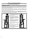
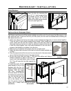
This model can be vented with 4” aluminum or stainless
steel ex vent and/or certied Type B Gas Vent. The
ue collar of the appliance will t inside of a standard
4” vent and may be fastened directly to the vent. Check
periodically that the vent is unrestricted and an adequate
draft is present when the unit is in operation.
Figure 10: Draft check.
Table 2: Minimum dimensions of replace for Sienna to be installed into.