


Installation
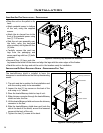
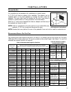
CHIMNEY INSTALLATION THROUGH WALL:
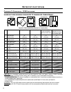
Here are four (4) methods of combustible wall chimney connector pass-throughs. Information was provided from NFPA 211.
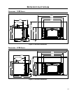
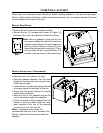
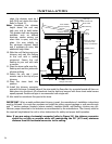
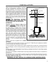
Method A. 12” (304.8 mm) Clearance to Combustible Wall Member:
Using a minimum thickness 3.5” (89 mm) brick and a ” (15.9 mm)
minimum wall thickness clay liner, construct a wall pass-through. The
clay liner must conform to ASTM C315 (Standard Specication for Clay
Fire Linings) or its equivalent. Keep a minimum of 12” (305 mm) of brick
masonry between the clay liner and wall combustibles. The clay liner
shall run from the brick masonry outer surface to the inner surface of the
chimney ue liner but not past the inner surface. Firmly grout or cement
the clay liner in place to the chimney ue liner.
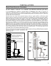
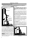
Method B. 9” (229 mm) Clearance to Combustible Wall Member: Using
a 6” (152 mm) inside diameter, factory-built Solid-Pak chimney section
with insulation of 1” (25.4 mm) or more, build a wall pass-through with a
minimum 9” (229 mm) air space between the outer wall of the chimney
length and wall combustibles. Use sheet metal supports, fastened
securely to wall surfaces on all sides, to maintain the 9” (229 mm) air
space. When fastening supports to chimney length, do not penetrate
the chimney liner (the inside wall of the Solid-Pak chimney). The inner
end of the Solid-Pak chimney section shall be ush with the inside of the
masonry chimney ue and sealed with a non-water soluble refractory
cement. Use this cement to also seal to the brick masonry penetration.
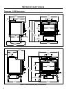
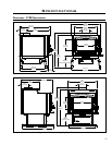
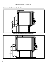
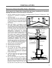
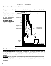
Method C. 6” (152.4 mm) Clearance to Combustible Wall Member:
Starting with a minimum 24 gauge (.024” [0.6 mm]) 6” (152.4 mm)
metal chimney connector and a minimum 24 gauge ventilated wall
thimble which has two air channels of 1” (25.4 mm) each, construct a
wall pass-through. There shall be a minimum 6” (152.4 mm) separation
area containing berglass insulation, from the outer surface of the wall
thimble to wall combustibles. Support the wall thimble and cover its
opening with a 24 gauge minimum sheet metal support. Maintain the
6” (152.4 mm) space. There should also be a support sized to t and
hold the metal chimney connector. See that the supports are fastened
securely to wall surfaces on all sides. Make sure fasteners used to secure
the metal chimney connector do not penetrate chimney ue liner.
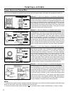
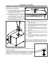
Method D. 2” (50.8 mm) Clearance to Combustible Wall Member: Start
with a solid-pak listed factory-built chimney section at least 12” (304 mm)
long, with insulation of 1” (25.4 mm) or more, and an inside diameter of
8” (2” [51 mm] larger than the 6” [152.4 mm] chimney connector). Use
this as a pass-through for a minimum 24 gauge single-wall steel chimney
connector. Keep solid-pak section concentric with and spaced 1” (25.4
mm) off the chimney connector by way of sheet metal support plates
at both ends of chimney section. Cover opening, and support chimney
section on both sides, with 24 gauge minimum sheet metal supports.
See that the supports are fastened securely to wall surfaces on all sides.
Make sure fasteners are used to secure chimney ue liner.
Twoventilated airchannels
each1 inch(25.4 mm).
Constructionof sheetsteel
Chimney
connector
Minimum6 inches
(152.4mm) glass
fiberinsulation
}
Sheetsteel
supportrs
Twoair channelseach
1inch (25.4mm)
}
Minimumchimney clearanceto sheetsteel
supportsand combustibles2 inches(50.8 mm)
Chimneyflue
Masonry
chimney
}
Minimum12 inches
(304.8mm) tocombustibles
Minimumclearance
12inches(304.8 mm)
ofbrick
Minimumchimneyclearance tobrick
andcombustibles2 inches(50.8 mm)
Chimney
connector
Fireclay liner
Masonry
chimney
}
}
ChimneyFlue
Factory-built
chimneylength
Chimneylength
flushwith inside
offlue
Solid-insulated,
listedfactory-built
chimneylength
Usechimney
manufacturer’s
partsto attach
connectorsecurely
}
Chimney
flue
Chimney
connector
Minimumclearance
9inches (228.6mm)
Airspace 9inches
(228.6mm) minimum
Minimumchimney clearancefrom masonryto sheet
steelsupports andcombustibles 2inches(50.8 mm)
Masonrychimney
}
Sheetsteel supports
Non-soluble
retractory
cement
NOTES:
1. Connectors to a masonry chimney, excepting method B, shall extend in one continuous section through the wall pass-through
system and the chimney wall, to but not past the inner ue liner face.
2. A chimney connector shall not pass through an attic or roof space, closet or similar concealed space, or a oor, or ceiling.
Figure 18: Chimney Through Wall - Method A.
Figure 19: Chimney Through Wall - Method B.
Figure 21: Chimney Through Wall - Method D.
Figure 20: Chimney Through Wall - Method C.
22