


Instruction Manual
HAS60E-IM-HW
June 2007
NGA 2000 CLD
4 - 5Maintenance and ServiceEmerson Process Management GmbH & Co.OHG
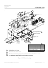
4-7 DETECTOR DISASSEMBLY
Refer to figure 4-3.
a. Reaction Chamber Removal
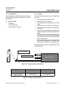
Disconnect the stainless steel tubing lines at the fittings.
Remove the (4) nuts holding the Detector Assembly to
the chassis. Disconnect the plug from connector J1 on
the Signal Board and remove the assembly from the
chassis.
NOTE
Care should be taken to avoid getting heatsink
compound on optical surfaces. If this substance
is removed during the disassembly process, a zinc-
oxide-filled, silicone grease (e.g. Dow Corning 340
or EG & G Wakefield Engineering´s Series 120
Thermal Joint Compound) be reapplied in the re-
assembly of this component.
Although the heater and thermostat can be removed to
facilitate handling, contact with the white heatsink com-
pound can be minimized by leaving these items in place.
Remove the (2) screws holding the top plate of the De-
tector, and move the plate along the wires and away from
the Detector.
Remove the (2) screws holding the tube assembly in
place. Hold the tubing with one hand while inverting the
Detector Housing with the other, allowing the Reaction
Chamber O-ring and window to be removed from below.
b. Reaction Chamber Installation
To reinstall, hold the housing in the inverted position while
sliding the Reaction Chamber O-ring and window into
position and the tubing into the slot in the housing. Hold
the Reaction Chamber in place while rotating the hous-
ing upright. Replace the hold-down screws.
NOTE
The procedure described above is for the purpose
of maintaining the relative positions of windows
and O-ring to the Reaction Chamber during instal-
lation.
Replace the top cap and screws. Reverse the removal
procedure to reinstall the Detector Assembly into the
Analyzer Module.
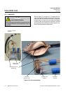
c. Photodiode Removal
Remove the Detector Assembly as described above. In-
vert the housing to access the mounting bracket. Re-
move the (3) screws and shoulder washers from the
bracket, insulating disk and bottom plate as a unit to mini-
mize the spread of the heatsink compound.
Remove the (2) screws holding the lower section of the
Detector Housing, then slide the section along the cable
and remove.
Remove the (2) screws holding the socket, thermistor
and photodiode in place, being careful not to lose the
washers that are used as shims.
Grasp the socket and photodiode base while slowly ro-
tating to separate the photodiode from the housing. Some
friction will be felt as an O-ring is used around the photo-
diode as a seal.
d. Photodiode Installation
To replace the photodiode, carefully remove the diode
from the green socket, and replace with a new one. Be-
fore mounting the new diode, the top cap of the enclo-
sure should be temporarily removed and the (2) screws
holding the Reaction Chamber loosened about two turns.
This allows air which is trapped between the O-ring seals
to escape when the diode is inserted. It also maintains
the position of the O-ring and window in the upper com-
partment.
The new photodiode should be slowly inserted into the
housing while gradually rotating the body. This allows the
O-ring to properly seat. Continue replacing screws, wash-
ers, thermistors, etc., with the thicker shim (washer) on
the opposite side of the socket from the thermistor.
Replace the lower section of the housing, then the bot-
tom cover, insulator and bracket with the shoulder wash-
ers and screws.
Re-tighten the screws in the Reaction Chamber (upper
section). Replace the top cap and its screws.
To reinstall in the Analyzer Module, reverse the proce-
dure for removal as indicated above.