


Instruction Manual
HAS60E-IM-HW
June 2007
NGA 2000 CLD
4 - 3Maintenance and ServiceEmerson Process Management GmbH & Co.OHG
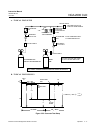
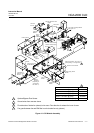
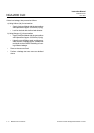
4 Optional Bypass Flow Sensor
3 Ground wires from ozonator shown
2 Flow direction of intake fan (shown) is into case. Flow direction of exhaust fan is out of case.
1 Fan guard between fan and EMI filter in on the intake fan only (shown).
Figure 4-1: CLD Module Assembly
Brief Description Part Number
Detector 200 cc/min. @ 5 psig 659754
Detector 200 cc/min. @ 2 psig 42716203
Detector 70 cc/min. @ 5 psig 42716204
Detector 70 cc/min. @ 2 psig 42716205
Detector assembly without capillary 659754X
5
5
Signal
Board
655580
Sample
Pressure
Sensor
655253
Ozone
Pressure
Sensor
655254
3
PCB Insulators
Flow Sensor
902931
Thermostat
657298
Ozonator
657719
Transistor
655264
Flow Balance
Metering Valve
903207
Sample
Regulator
(depending on
configuration,
see Table 1-1)
Computer Analysis
Board 658350
Insulator
LON/Power
Module
Power Supply Board
657520
Detector Case Insulator
Detector Assembly, see Figure 4-3
(PN depending on configuration)
Driver
Board
655620
NO/NOx Solenoid Valve
659477
Pressure Switch 655215
Fan Guard
Fan Guar
d
EMI Shield
Converter Assembly 655250
See Figure 4-2
-
Glass Tube
Connectors
Fan
655245
2
Ozonator Power Supply
657716
Fuse, Power
903347
1
4