


NGA 2000 CLD
Instruction Manual
HAS60E-IM-HW
June 2007
4 - 2 Maintenance and Service Emerson Process Management GmbH & Co.OHG
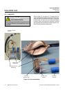
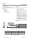
4-2 FUSES
The main power fuse may require replacement.
NOTE
Before replacing the fuse, remove power to the
Analyzer Module.
See figure 2-3 for the location of the main power fuse
[T 6A 250 V (6x32 mm)], which protects 24 VDC input to
the module.
NOTE
Use only fuses of the correct type and current rat-
ings as replacements. Using repaired fuses and
short circuiting of fuse holders is prohibited.
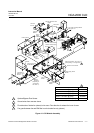
4-3 FANS
Refer to figure 4-1. To replace either rear panel fan, re-
move the cover of the Analyzer Module and then the
rear panel. Disconnect connectors and remove screws.
Assemble in reverse order.
4-4 OZONATOR
Refer to figure 4-1. To replace the ozonator, remove the
two large straps and all tie-wraps, and disconnect the
one electrical connection. Reassemble in reverse order.
4-5 PRINTED CIRCUIT BOARDS
All four printed circuit boards can be replaced, if neces-
sary. Refer to figure 4-1 for location of the Driver, Power
Supply, Signal and Computer Boards.
To remove any PCB (except the Computer Board), dis-
assemble the enclosure side first. Ribbon and other
cables are long enough to allow the entire side to be
folded out from the remainder of the components. This
makes PCB removal much simpler.
The electronic parts of the Analyzer Module can
be irreparably damaged if exposed to electrostatic
discharge (ESD).
The instrument is ESD protected when the covers
have been secured and safety precautions ob-
served. When the housing is open, the internal
components are not ESD protected anymore.
CAUTION