


Instruction Manual
HAS60E-IM-HW
June 2007
NGA 2000 CLD
3 - 1OperationEmerson Process Management GmbH & Co.OHG
SECTION 3
OPERATION
3-1 OVERVIEW
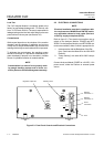
Once the CLD has been correctly assembled and in-
stalled, the analyzer is ready for operation.
Before operating the system, verify that the Leak Checks
have been performed in accordance with Section 2-4.
In this section, all operations for starting up the analyzer
are explained. For more detailed information about soft-
ware screens see associated Software Manual.
For the remainder of this section, Analyzer Module inter-
connection with a Platform or some interfacing compo-
nent is assumed. Display and Keypad information refers
to that which the user can expect to see and do with
regard to the Front Panel of the Platform.
Depending from the software version that is installed,
menu layout can change, whereas the principle of op-
eration always stays the same.
This instruction manual is based on menus of software
version 3.7.1.
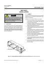
3-2 STARTUP & INITIALIZATION
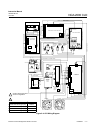
Apply LON connection and power to the CLD Analyzer
Module. If it is associated with a Platform, do this by
plugging in the Platform to a power source. The Plat-
form has no ON/OFF power button. Once power has
been supplied to the Platform, the CLD Analyzer Module
will be energized.
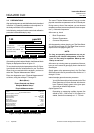
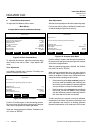
After switching on the CLD, the analyzer will begin its
booting procedure which is apparent on the CLD screen.
The first part of the initialization procedure is a self check
of the software and analyzer components. Various dis-
plays will show the status of the initialization including
revision notes, "Initializing network interface", "Search-
ing for nodes", "Scanning Module 2: CLD, 12 % Com-
plete", and "Calculating bindings".
If the user´s system contains only one Analyzer Module,
all system components, the Controller Board and the
network "self-install" (bind together) during initial startup.
If the system contains more than one Analyzer Module,
the startup sequence will interrogate the network to lo-
cate and identify all components on the network. The
user will have to bind appropriate combinations of com-
ponents after the startup sequence. See the Platform
manual for instructions on binding combinations of mod-
ules.
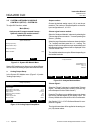
Pressing the F1 key during initializing will reset the CLD
brightness and contrast to factory settings. Pressing the
F3 softkey will abort the network initializing, aborting any
connection to other analyzers. In that case, only the
menus of the local analyzer will be available.
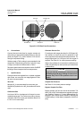
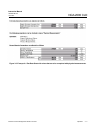
At the end of the initializing routine the "measure" screen
will display. This screen is the access to all other chan-
nels, menus and submenus. The actual display may dif-
fer from that shown depending on any custom configu-
ration.
After the warm-up period (about one hour for the CLD
Analyzer Module), all modules are completely functional.
Establish that correct ozonator air pressure and sample
flow rate are within specifications (see Section 1-5). Cali-
brate and adjust converter efficiency, and begin opera-
tion as the following sections indicate.