


Split System Models
59
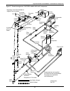
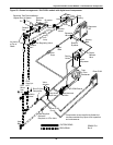
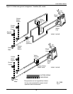
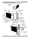
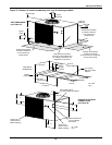
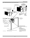
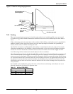
Figure 31 Refrigerant piping diagram
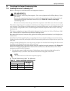
7.3.2 Quick Connect Fittings
Be especially careful when connecting the quick connect fittings. Read through the following steps
before making the connections.
1. Remove protector caps and plugs.
2. Carefully wipe coupling seats and threaded surfaces with a clean cloth.
3. Lubricate the male diaphragm and synthetic rubber seal with refrigerant oil.
4. Thread the coupling halves together by hand to ensure that the threads mate properly.
5. Tighten the coupling body hex nut and union nut with the proper sized wrench until the coupling
bodies “bottom out” or until a definite resistance is felt.
6. Using a marker or pen, make a line lengthwise from the coupling union nut to the bulkhead.
7. Tighten the nuts an additional quarter turn; the misalignment of the lines shows how much the
coupling has been tightened. This final quarter turn is necessary to ensure that the joint will not
leak. Refer to Table 24 for torque requirements.
8. Add charge for the additional piping (refer to Table 22).
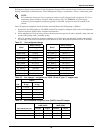
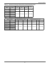
Table 24 Line coupling sizes
Model
(Tons)
Line Size
OD Cu, in.
Coupling
Size
Torque
lb-ft.
33/8 #610-12
5 1/2 & 5/8 #10 35-45
3 7/8 #11 35-45
5 1-1/8 #12 50-65
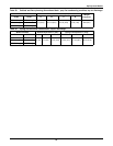
Table 25 Equivalent lengths (feet) for various pipe fittings
Copper Pipe
OD in.
90 Degree
Elbow Copper
90 Degree
Elbow Cast
45 Degree
Elbow Tee
Gate
Valve
Globe
Valve
Angle
Valve
1/2 0.8 1.3 0.4 2.5 0.26 7.0 4.0
5/8 0.9 1.4 0.5 2.5 0.28 9.5 5.0
3/4 1.0 1.5 0.6 2.5 0.3 12.0 6.5
7/8 1.45 1.8 0.8 3.6 0.36 17.2 9.5
1-1/8 1.85 2.2 1.0 4.6 0.48 22.5 12.0
1-3/8 2.4 2.9 1.3 6.4 0.65 32.0 16.0
1-5/8 2.9 3.5 1.6 7.2 0.72 36.0 19.5
Refrigerant trap = 4 times equivalent length of pipe per this table
NOTE
When hard piping is used, complete all piping and evacuate lines before
connecting quick connects.
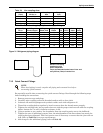
Evaporator
Condensing unit
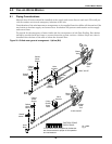
Suction Line Piping
Condensing unit
above evaporator
Traps recommended at the base of riser and
every 25 feet (7.6m) of vertical rise.