


Installation (Applicable to all Models)
21
2.8 Balancing the Air Distribution
2.8.1 Under-Floor Discharge Systems
The systems are designed for constant air delivery, therefore any unusual restrictions within the air
circuit must be avoided. For under-floor air distribution, observe the following guidelines:
• Select the air supply grilles and perforated panels for the raised floor to ensure minimum loss of
pressure in the circuit. Air volume dampers on grilles, which extend several inches below the sur-
face of the raised floor, are usually detrimental to airflow.
• Consideration of the height of the damper on the grille in conjunction with the floor height will
determine whether this type of grille may be used.
• The grilles used in raised floors vary in size, the largest being approximately 18" x 6"
(457 x 152 mm). A larger grille size would be detrimental to the structural capacity of the raised
floor panel. An 18" x 6" (457 x 152 mm) heavy duty, pencil-proof type grille typically has 56 square
inches (0.036 m
2
) of free area.
• Perforated panels are available from various manufacturers of raised floors. These panels are
usually 2' x 2' (610 x 610 mm) square and have a nominal free area of approximately 108 to 144
square inches (0.07 to 0.09 m
2
). Use caution in selecting perforated panels as some manufacturers
have only 36 to 40 square inches (0.023 to 0.026 m
2
) of free area, requiring four times as many
panels.
• Avoid floor elevations below 7-1/2" (190.5 mm), loosely installed flooring systems, and below-floor
obstructions such as: electrical wiring chases, unusually long electronic system cables, or piping
clusters.
• Always check specifications of the floor supplier before specifying the total number of perforated
panels and grilles required to handle the air flow. The proper specifications for grilles and perfo-
rated panels should indicate the total free area required for air delivery rather than the number
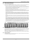
of panels and grilles. (See Table 3 for recommended free area required for each model.) This table
indicates the recommended free area based on having the supply air grilles and perforated panels
sized to handle approximately 75% of the total cubic feet per minute (CFM) of the units at a veloc-
ity of 550 to 600 ft./min. (2.8 - 3.1 m/s). The remaining 25% of the air flow in the raised floor
passes through cable cutouts, cracks between the panels, and other leakage areas.
2.8.2 Ducted Applications
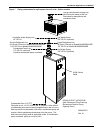
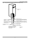
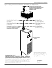
For ducted supply applications on upflow units, the duct work should be attached to the blower dis-
charge flanges of the unit. For ducted return air applications, the duct work should be attached to the
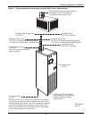
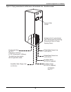
filter box flanges on upflow rear return units and on the unit top flange for downflow units. Refer to
Figure 2 for information on upflow units and to Figure 3 for downflow units.
The duct work on upflow units must allow access to the motors/blowers for maintenance. The duct
work on upflow units must be designed within the capacity of the unit, otherwise air flow and perfor-
mance will be compromised.
2.8.3 Plenum Installation
A solid plenum or plenum with discharge grille(s) may be installed. The plenum and instructions for
its installation ship separately from the unit.
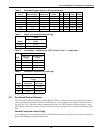
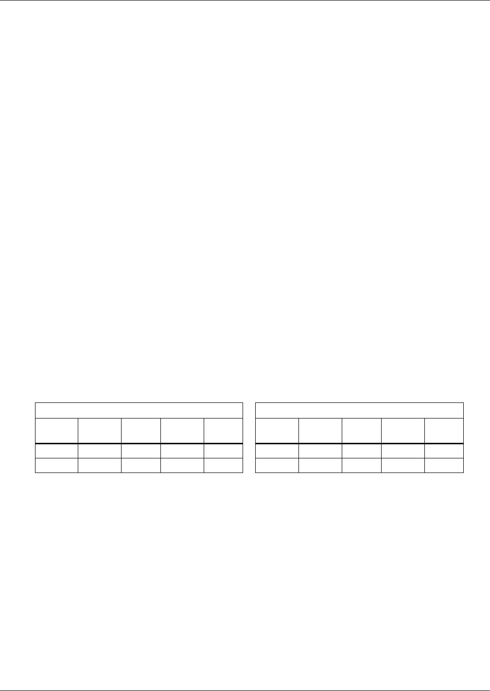
Table 3 Recommended free area ft
2
(m
2
) for grilles or perforated panels at output velocities of
550 and 600 fpm (2.8 and 3.1 m/s)
50 Hz Units 60 Hz Units
Model
550
FPM
2.8
m/s
600
FPM
3.1
m/s Model
550
FPM
2.8
m/s
600
FPM
3.1
m/s
3-ton 2.5 (0.01) 2.3 (0.01) 3-ton 2.5 (0.01) 2.3 (0.01)
5-ton 3.5 (0.02) 3.3 (0.02) 5-ton 3.8 (0.02) 3.5 (0.02)