


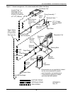
Air-Cooled Models—Self-Contained Compressor
28
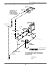
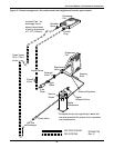
Variable Fan Speed Charging
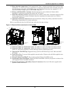
1. Check unit nameplate for refrigerant type to be used. Unit control configurations differ depending
on refrigerant type.
2. Refrigerant charging requires unit operation. Refer to 2.9 - Checklist for Completed
Installation.
3. Calculate the amount of charge for the system. Refer to the unit, condenser and refrigerant line
charge data in Tables 6, 7, 8 and 9.
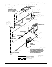
4. Weigh in as much of the system charge as possible before starting the unit.
5. Turn on unit disconnect switch. Operate the unit for 30 minutes using the charging function for
the system in the diagnostic section of the Liebert iCOM control (see Liebert iCOM user manual,
SL-18835). The charging function operates the compressor at full capacity and energizes the
blower motor and the liquid line solenoid valve. The reheat and humidifier are disabled. A
minimum 20psig (138kPa) must be established and maintained for the compressor to operate.
The charging function can be reset as many times as required to complete unit charging.
6. Charge the unit until the liquid line sight glass becomes clear. Then add one additional pound
(2.2kg) of refrigerant.
7. As head pressure builds, the variable fan speed controlled condenser fan begins rotating. The fan
will run at full speed when sufficient head pressure is developed—fan starts to rotate at 190 psig
(1310 kPA) and is full speed at 250 psig (1724 kPA).
!
CAUTION
Risk of improper refrigerant charging. Can cause equipment damage.
Refrigerant R407C is a blend of three components and must be introduced and charged from
the cylinder only as a liquid.
When adding liquid refrigerant to an operating system, it may be necessary to add the
refrigerant through the compressor suction service valve. Care must be exercised to avoid
damage to the compressor. Emerson recommends connecting a sight glass between the
charging hose and the compressor suction service valve. This will permit adjustment of the
cylinder hand valve so that liquid can leave the cylinder while allowing vapor to enter the
compressor.
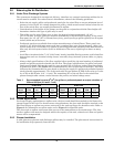
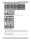
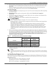
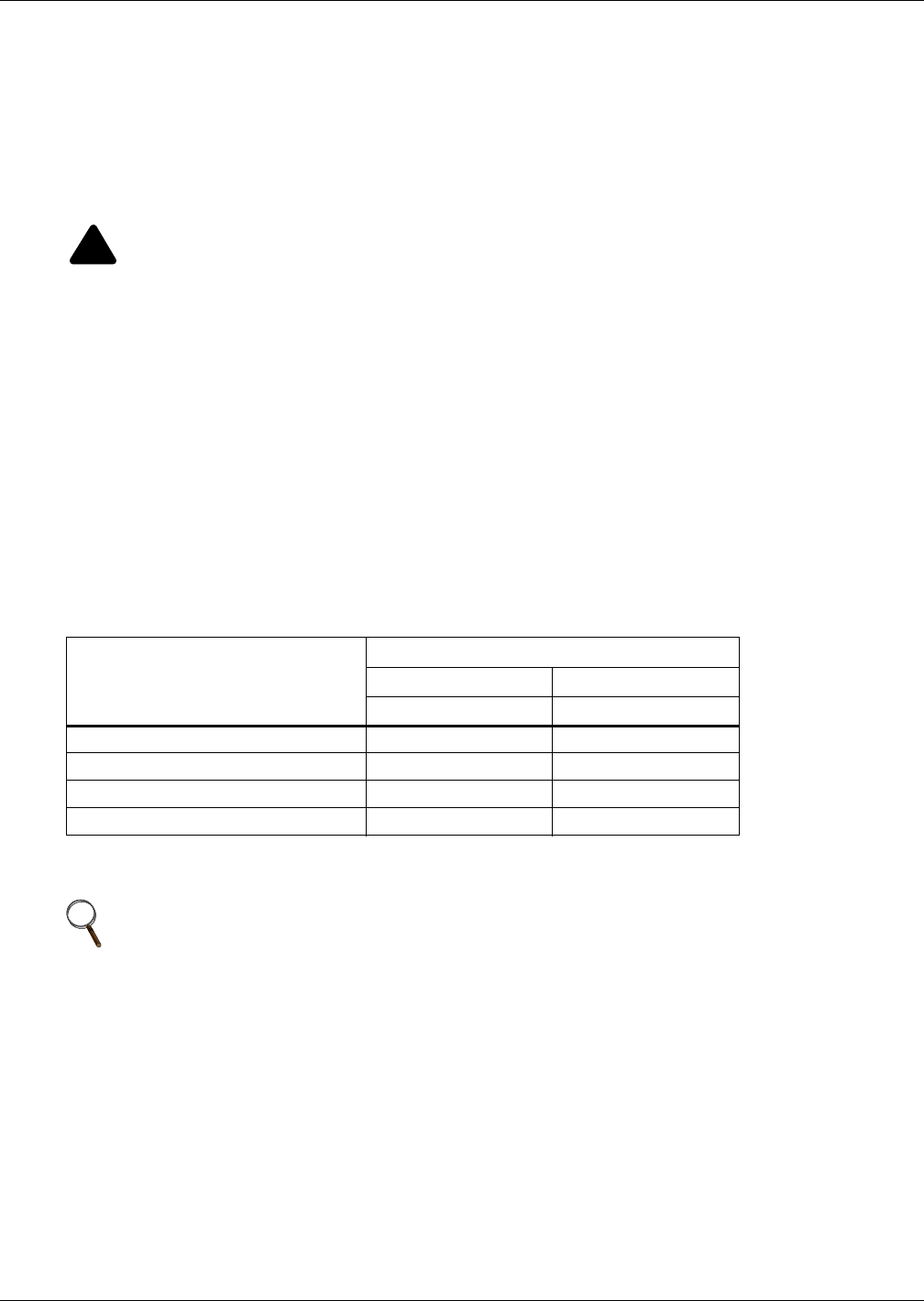
Table 10 Fan speed suction pressure transducer settings
Function
R-407C
Gauge (Sea Level) Absolute
psiG (kPa) psiA (kPa)
Pump-Down Cutout 20 (138) 35 (241)
Pump-Down Reset 65 (448) 80 (552)
Minimum to Start-Cooling 35 (241) 50 (344)
Low-Pressure Cutout (DX only) 52 (358) 67 (461)
NOTE
A digital scroll compressor will have a clear sight glass only when operating at 100% capacity.
When operating below 100%, the sight glass may show bubbles with each 15-second unloading
cycle.