


iii
FIGURES
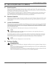
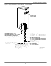
Figure 1 Removing Challenger from skid. . . . . . . . . . . . . . . . . . . . . . . . . . . . . . . . . . . . . . . . . . . . . . . . . . . . . 6
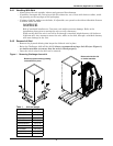
Figure 2 Upflow (BU) cabinet dimensions . . . . . . . . . . . . . . . . . . . . . . . . . . . . . . . . . . . . . . . . . . . . . . . . . . . . 7
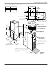
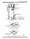
Figure 3 Downflow (BF) cabinet dimensions . . . . . . . . . . . . . . . . . . . . . . . . . . . . . . . . . . . . . . . . . . . . . . . . . . 8
Figure 4 Piping connections for air-cooled units - Downflow models . . . . . . . . . . . . . . . . . . . . . . . . . . . . . . 10
Figure 5 Piping connections for air-cooled units - Upflow models . . . . . . . . . . . . . . . . . . . . . . . . . . . . . . . . 11
Figure 6 Piping connections for split system fan coil units - Downflow models . . . . . . . . . . . . . . . . . . . . . 12
Figure 7 Piping connections for split system fan coil units - Upflow models . . . . . . . . . . . . . . . . . . . . . . . 13
Figure 8 Piping connections for water/glycol and GLYCOOL units - Downflow models . . . . . . . . . . . . . . 14
Figure 9 Piping connections for water/glycol and GLYCOOL units - Upflow models . . . . . . . . . . . . . . . . . 15
Figure 10 Piping connections for chilled water self-contained units - Downflow models . . . . . . . . . . . . . . . 16
Figure 11 Piping connections for chilled water self-contained units - Upflow models . . . . . . . . . . . . . . . . . 17
Figure 12 Electrical connections . . . . . . . . . . . . . . . . . . . . . . . . . . . . . . . . . . . . . . . . . . . . . . . . . . . . . . . . . . . . 19
Figure 13 Electrical field connections for Liebert iCOM . . . . . . . . . . . . . . . . . . . . . . . . . . . . . . . . . . . . . . . . . 20
Figure 14 Air-cooled condensers . . . . . . . . . . . . . . . . . . . . . . . . . . . . . . . . . . . . . . . . . . . . . . . . . . . . . . . . . . . . 24
Figure 15 General arrangement—Air-cooled models with fan speed control. . . . . . . . . . . . . . . . . . . . . . . . . 29
Figure 16 General arrangement—Air-cooled models with digital scroll and fan speed control . . . . . . . . . . 30
Figure 17 General arrangement—Air-cooled models with Liebert Lee-Temp . . . . . . . . . . . . . . . . . . . . . . . . 33
Figure 18 General arrangement—Air-cooled models with digital scroll and Lee-Temp . . . . . . . . . . . . . . . . 34
Figure 19 General arrangement—Water-cooled models with scroll compressor . . . . . . . . . . . . . . . . . . . . . . 36
Figure 20 General arrangement diagram—Water-cooled models with digital scroll . . . . . . . . . . . . . . . . . . 37
Figure 21 Johnson Controls valve adjustment. . . . . . . . . . . . . . . . . . . . . . . . . . . . . . . . . . . . . . . . . . . . . . . . . 38
Figure 22 Metrex Valve adjustment . . . . . . . . . . . . . . . . . . . . . . . . . . . . . . . . . . . . . . . . . . . . . . . . . . . . . . . . . 39
Figure 23 Drycoolers and pump packages . . . . . . . . . . . . . . . . . . . . . . . . . . . . . . . . . . . . . . . . . . . . . . . . . . . . 47
Figure 24 Pump packages—expansion tank . . . . . . . . . . . . . . . . . . . . . . . . . . . . . . . . . . . . . . . . . . . . . . . . . . 48
Figure 25 General arrangement—Glycol-cooled models with scroll compressor . . . . . . . . . . . . . . . . . . . . . . 49
Figure 26 General arrangement—Glycol-cooled models with digital scroll . . . . . . . . . . . . . . . . . . . . . . . . . . 50
Figure 27 General arrangement—GLYCOOL models with scroll compressor. . . . . . . . . . . . . . . . . . . . . . . . 51
Figure 28 General arrangement—GLYCOOL models with digital scroll compressor. . . . . . . . . . . . . . . . . . 52
Figure 29 Chilled water general arrangement - Upflow (BU). . . . . . . . . . . . . . . . . . . . . . . . . . . . . . . . . . . . . 54
Figure 30 Chilled water general arrangement - Downflow (BF) models . . . . . . . . . . . . . . . . . . . . . . . . . . . . 55
Figure 31 Refrigerant piping diagram . . . . . . . . . . . . . . . . . . . . . . . . . . . . . . . . . . . . . . . . . . . . . . . . . . . . . . . 59
Figure 32 Outdoor air-cooled condensing unit—horizontal air discharge models . . . . . . . . . . . . . . . . . . . . . 60
Figure 33 Outdoor air-cooled condensing unit—top air discharge models . . . . . . . . . . . . . . . . . . . . . . . . . . . 62
Figure 34 Electrical field connections, prop fan condensing module . . . . . . . . . . . . . . . . . . . . . . . . . . . . . . . 64
Figure 35 Detail of ceiling hanging bracket . . . . . . . . . . . . . . . . . . . . . . . . . . . . . . . . . . . . . . . . . . . . . . . . . . . 66
Figure 36 3-ton centrifugal air-cooled condensing unit dimensional data & piping connections . . . . . . . . . 67
Figure 37 3-ton centrifugal air-cooled condensing unit (con't.) . . . . . . . . . . . . . . . . . . . . . . . . . . . . . . . . . . . . 68
Figure 38 5-ton centrifugal air-cooled condensing unit dimensional data . . . . . . . . . . . . . . . . . . . . . . . . . . . 69
Figure 39 5-ton centrifugal air-cooled condensing unit dimensional data (con't.) . . . . . . . . . . . . . . . . . . . . . 70
Figure 40 Split systems general arrangement . . . . . . . . . . . . . . . . . . . . . . . . . . . . . . . . . . . . . . . . . . . . . . . . . 71
Figure 41 3-ton water/glycol-cooled condensing unit. . . . . . . . . . . . . . . . . . . . . . . . . . . . . . . . . . . . . . . . . . . . 73
Figure 42 3-ton water/glycol-cooled condensing unit (con't.). . . . . . . . . . . . . . . . . . . . . . . . . . . . . . . . . . . . . . 74
Figure 43 5-ton water/glycol-cooled condensing unit dimensional data . . . . . . . . . . . . . . . . . . . . . . . . . . . . . 75
Figure 44 5-ton water/glycol-cooled condensing unit (con't.). . . . . . . . . . . . . . . . . . . . . . . . . . . . . . . . . .
. . . . 76