


Installation (Applicable to all Models)
20
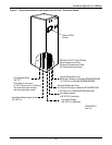
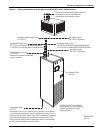
15. Heat rejection connection. Field-supplied 24V Class 1 wiring to interlock heat rejection from
pigtails 70 + 71 which are factory-connected to compressor side switch (self-contained units only)
or to GLYCOOL relay (K11, GLYCOOL units only). On Dual Cool units only, pigtails 72 + 73
connect auxiliary cooling source to GLYCOOL relay K11.
16. Reheat and Humidifier Lockout. Optional emergency power lockout of reheat and/or
humidifier: connections provided for remote 24V AC source.
17. Main Fan Auxiliary Switch. Optional main fan auxiliary side switch. Terminals located in field
wiring compartment for remote indication that the evaporator fan motor/unit is on. Field to
connect 24V maximum.
18. Optional Condensate Alarm (Dual Float Condensate Pump only). Relay terminals located in
field wiring compartment for remote indication.
Refer to specification sheet for full load amp. and wire size amp. ratings.
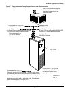
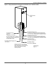
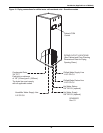
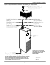
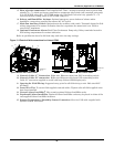
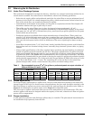
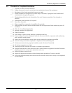
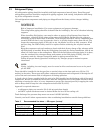
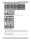
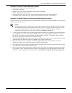
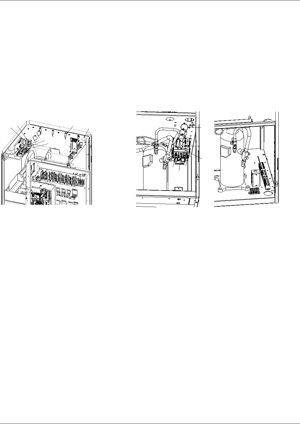
Figure 13 Electrical field connections for Liebert iCOM
19. Network Cable “C” Connection. Eight-wire Ethernet cable from U2U networking switch.
20. Network Cable “D” connection. Eight-wire Ethernet cable from U2U networking switch.
Cable “D” connection supplied on units with large Liebert iCOM display only.
21. Opening for Field Wiring. Suggested entry point for all field wiring to unit. Hole size Ø2.5"
(63.5mm)
22. Loose Wire Ties. To secure field-supplied network cables. Tighten after all field-supplied wires
have been installed.
23. Vacant Liebert IntelliSlot
®
. May contain optional Liebert IntelliSlot cards.
24. Populated Liebert IntelliSlot. Optional Liebert IntelliSlot cards may be placed in either of the
two supplied Liebert IntelliSlot locations.
25. Remote Temperature / Humidity Sensor Connection. Six-wire CAN cable supplied with
optional remote T/H sensor
DPN001733
Rev. 0
23
24
22
21
20
19
25
DPN001734
Rev. 0
22
24
23
20
19
25
Upflow Models with Liebert iCOM Downflow Models with Liebert iCOM