


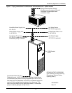

Air-Cooled Models—Self-Contained Compressor
25
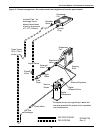
3.3 Refrigerant Piping
All refrigeration piping should be installed with high temperature brazed joints. Prevailing good
refrigeration practices should be employed for piping supports, leak testing, dehydration and charg-
ing of the refrigeration circuits.
Unit refrigeration components and piping are shipped from the factory with a nitrogen holding
charge.
NOTICE
Risk of improper installation. Can cause equipment and property damage.
The refrigeration piping should be isolated from the building by the use of vibration isolating
supports.
When installing field piping, care must be taken to protect all refrigerant lines from the
atmosphere, especially when using refrigerants with POE oils. Do not allow the piping to
stand open to air for more than 15 minutes. Units designed for R407C have a compressor that
contains POE oil that is very hygroscopic; that is, it quickly absorbs water from the air. The
longer the compressor piping is left open to air, the harder it will be to fully evacuate. If left
open too long, the POE oil may need to be replaced before achieving the required vacuum
level.
Keep the evaporator unit and condenser closed with their factory charge of dry nitrogen while
all field piping is installed. Keep the field piping clean and dry during installation, and do not
allow it to stand open to the atmosphere. When all the field interconnecting piping is in place,
vent the condenser dry nitrogen charge and connect to the field piping. Finally, vent the
evaporator unit dry nitrogen charge and make its piping connections last.
Follow all proper brazing practices including a dry nitrogen purge to maintain system
cleanliness.
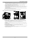
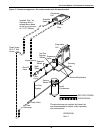
Traps should be installed in the hot gas line on vertical risers at the base and every 25 feet (7.6
meters) in elevation. These traps will collect condensed refrigerant and refrigerant oil during the off
cycle of the unit and ensure flow of refrigerant oil during operation.
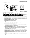
A check valve is factory-supplied with the unit to be field-installed on the discharge side of the scroll
compressor. Be sure to install the check valve with the refrigerant flow in the proper direction. When
soldering or brazing the valve, it is very important to protect the internal parts by wrapping the valve
with a damp cloth to keep the valve temperature below 250°F (121°C).
Approval is required whenever:
• a refrigerant piping run exceeds 150 ft. (46 m) equivalent length
• an R407C system condenser must be located below the level of the cooling coil.
Total discharge line pressure drop must not exceed 10 PSIG (69 kPa).
Consult your local Liebert representative when considering installations outside these guidelines.
NOTE
Piping, including inverted trap(s), must be routed to allow unobstructed access to the panel
per the NEC.
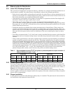
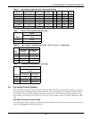
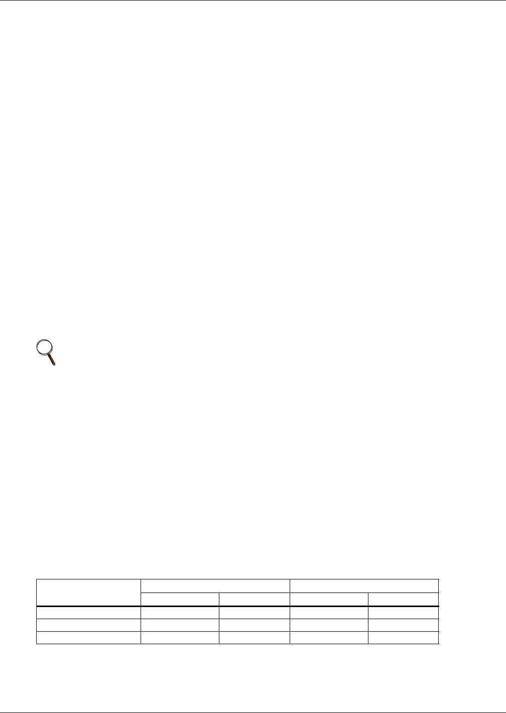
Table 5 Recommended line sizes — OD copper (inches)*
Equivalent Length
3.5-ton 042A (040A) 5-ton 067A (065A)
Hot Gas Line Liquid Line Hot Gas Line Liquid Line
50 ft. (15 m) 5/8 1/2 7/8 1/2
100 ft. (30 m) 3/4 1/2 7/8 5/8
150 ft. (45 m) 3/4 5/8 7/8 5/8
*Recommended vertical line sizes must be used for proper oil return at all cooling and dehumidification steps.