


1.2 Wiring
3
1.2 Wiring
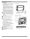
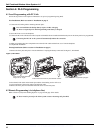
1. Zone Wiring
Zones can be wired for Normally Open, Normally Closed Contacts with Single-
end-of-line (SEOL) resistors or Double End-of-Line (DEOL) resistors. Observe
the following guidelines
•For UL/ULC listed installations use SEOL or DEOL only.
• Minimum 22 AWG wire, maximum 18 AWG
•Do NOT use shielded wire
• Wire run resistance shall not exceed 100Ω. Refer to the chart below.
• Section [009] Selects Hardwired Zone Definition
• Sections [133], [134] Opt [14] selects Normally Closed
• Sections [133], [134] Opt [15] selects SEOL resistors
• Sections [133], [134] Opt [16] selects DEOL resistors.
Zone Status - Loop Resistance/Loop Status
• Fault - 0Ω (shorted wire/loop)
• Secure - 5600Ω (contact closed)
• Tamper - infinite (broken wire, open)
• Violated - 11,200Ω (contact open)
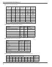
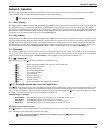
2. PGM/Aux Power Wiring
PGMs switch to ground when activated by control panel.
Connect the plus side of the device to be activated to the AUX+ Terminal. Con-
nect the minus terminal to the PGM. Each PGM can provide 50mA output.
NOTE: The control panel can provide a maximum of 100mA of AUX current for
PGMs, relays, LED’s etc. Min/Max operating voltages for PGMs, relays and
modules is 10.2V
DC - 13.75VDC
NOTE: Battery Voltage (6.0-8.4VDC) is boosted internally to supply 12VDC on
the AUX+ output by setting Sect[014] Opt[4] to ON. This option must be
enabled for PGMs used in UL/ULC Residential Burg installations. This output
can NOT be used for UL/ULC Fire installations.
LED output with
current limiting
resistor and
optional Relay
driver output
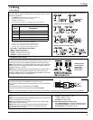
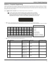
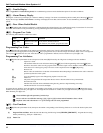
3. Telephone Line Wiring
Wire the telephone connection terminals (TIP, Ring, T-1, R-1) to an RJ-31x
Connector as indicated. Use 24 AWG wire minimum for wiring.
For connection of multiple devices to the telephone line, wire in the sequence
indicated.
Communication format is programmed in section [350].
Telephone Call Directions are programmed in section [351]-[376].
Note: For UL Listed Installations,the Installer must verify the communication format with the supervising station at the time of the installation.
4. Battery 5. AC Wiring
A 1500 mAHr Ni-Mh battery pack is included to meet standby power require-
ments
NOTE: UL/ULC Residential Burglary installations require 4 Hr. power standby
time plus 4 minutes alarm annunciation.
NOTE: UL/ULC Residential Fire installations require 24 Hr. power standby
plus 5 minutes alarm annunciation
NOTE: Battery life is 4-5 years under typical operating conditions. Battery
capacity deteriorates with age and number of charge/discharge cycles.
Replace battery every 4-5 years.
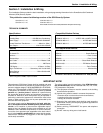
AC Transformer Requirements:
Primary:120VAC, 50/60Hz., 0.33A
240VAC, 50/60Hz., 0.165A
Secondary: 16.5VAC/20VA
The following Transformers shall be used:
UL Listed Installations - PTD1620U, PTD1640U (60Hz.)
ULC Listed installations - PTD1620, PTD1640 (60Hz.)
EU Installations - PTD1620T-EU (50 Hz.)
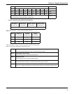
Burglary Zone Wiring Chart
Wire
Gauge
Max wire Length to End-of-line Resistor
(feet/meters)
22 3000 / 914
20 4900 / 1493
19 6200 / 1889
18 7800 / 2377
Figures are based on maximum wiring resistance of 100Ω
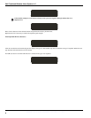
Normally Closed Loops - Do NOT use for UL Installations
Single End-of-Line Resistor Wiring
Double End-of-Line Resistor Wiring
I/O
I/O
T-1
R-1
TIP
RING
RJ-31X
RED
GRN
BRN
GRA
WWW.DIYALARMFORUM.COM