


Self Contained Wireless Alarm System v1.0
2
1.1 Installation:
1
2
3.
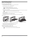
If required, separate the front and back covers by remov-
ing the cover screw then inserting a small slotted screw
driver between the front and back covers and gently twist
the screwdriver to separate.
Route Telephone line wiring, I/O Wiring, and AC power
through a single or double ganged junction box and
through cutout in the back cover see Fig. 2 Mounting &
Wiring details. If Programming with DLS, See “4.1 Local
Programming with PC-Link” on page 10. If using Template
programming or Advanced Keypad programming continue
to the next step.
Secure the back cover to the junction box with the screws
provided (2 screws for single gang box or 4 screws for a
double ganged box). For drywall (surface mount) secure
to wall using 4 #6 3/4” wood screws and drywall plugs.
See figure 2, Mounting & Wiring Details for hole locations.
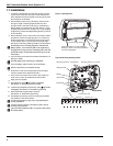
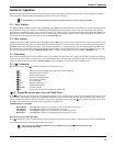
Figure 1, Opening Cover
If mounting unit on a double ganged box with the wall
tamper feature, secure the back plate to the right side of
the ganged box using the center mounting holes. This will
provide the tamper switch with unobstructed access to the
wall surface
4. Connect wiring to the terminals indicated. See Section 1.2
Wiring for details.
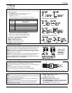
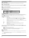
Figure 2, Mounting & Wiring Details
Do NOT apply power until wiring is completed.
5. Connect battery cable connector to the PC Board.
Ensure connector key is oriented correctly.
6.
7.
8.
9.
10.
11.
12.
Position the cover onto the back plate. Ensure tamper
switch is positioned for effective operation.
Insert cover in the lower slot at a 35° to 55° angle then
snap cover in place. An audible click will be heard.
Apply power to System.
Enroll devices. Enter [
][8][Installer Code][898].
See Section 2, Wireless Device Enrollment.
If performing Template programming, enter [
][8][Installer
Code][899]. See Section 3, Template Programming
Enter Advanced Programming if required.
See Section 5, Advanced Programming.
Test System by violating zones and verifying successful
transmission to the central station.
See DLS Programming on page 10 for reprogramming an
existing Installation.
AC Power must be present for the Alarm system to answer
Incoming calls from DLS
After the initial installation 24 Hrs. is required to fully charge
the standby battery.
Insert Screwdriver in slots indicated
Gently pry open cover with screwdriver
until cover separates
Remove cover screw
Tamper Switch
Third Hand
Cover screw hole
Strain Relief
Battery
Tamper Switch
Mounting Holes (6) - Ganged box Mounting Holes (4) - Drywall
Wiring Access
Telephone Line
12 V
DC
PGM/ZonesAC Power
Red Grn Gra Brn
AC AC Aux 1 I/O 2+- Ring Tip R-1 T-1
WWW.DIYALARMFORUM.COM