


2.10. REFUELING
We recommend that you do not let the hopper drop below ¼ full. If the reload lid stays open for more than
3 minutes, a warning will appear. To restart, press the “RESET” button, and then press the “MODE” button
to start the unit on Manual or Thermostatic mode.
KEEP HOPPER LID CLOSED AT ALL TIMES EXCEPT WHEN REFILLING. THE HOPPER MAY BE FILLED
WHILE THE STOVE IS OPERATING. DO NOT OVERFILL HOPPER.
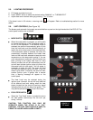
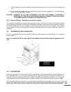
2.11. SHUTDOWN PROCEDURE
Turning your Drolet stove off is a matter of pressing the “MODE” control panel switch, until the “OFF” led goes
on. The blowers will continue to operate until internal firebox temperatures has fallen to a preset level.
2.12. SAFETY FEATURES
a. If the exhaust blower fails, the flue is blocked or a back draft occurred inside the flue, an air pressure switch
will automatically shut down the auger and the combustion blower. Then, a warning message will
appear. This safety feature is to prevent the unit from burning fuel when the exhaust blower has failed,
therefore preventing combustion fumes from spilling into the room.
b. If the temperature in the auger rises beyond a certain acceptable level, a high temperature switch located on
the auger housing will stop the fuel feed system and a warning will appear.
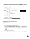
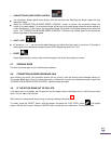
CODE
BEFORE RESETING
TO RESET
H
Heat exchanger and/or exhaust system
is/are clogged. Refer to the owner‟s
manual for maintenance procedures.
Press simultaneously for 2 seconds the mode
and reset.
*** After 3 attempts, reset is no longer possible, call SBI technical support.
2.13. OPERATING THE STOVE USING A THERMOSTAT
A thermostat may help you maintain a constant house temperature automatically. A millivolt thermostat is
required. A fixed wall mount or hand held model can be used. The control panel can be set up three ways to
operate your stove in thermostatic mode.
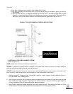
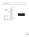
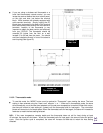
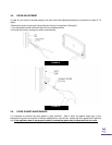
2.13.1. Thermostat Installation
Unplug the stove from the power outlet.
Connect two thermostat wires to the terminal block located on the lower right side of the back of the stove.
To do so, loosen the two screws and insert the wires in the terminals. Tighten the two screws. (See
figure 18)
The size of wires will vary with the distance:
DISTANCE DIAMETER
20 ft 18GA
30 ft 16GA
40 ft 14GA
50 ft 12GA