


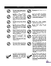
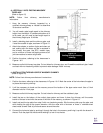

DO NOT CONNECT THIS UNIT TO A CHIMNEY FLUE SERVING ANOTHER APPLIANCE.
DO NOT INSTALL A FLUE DAMPER IN THE EXHAUST VENTING SYSTEM OF THIS UNIT.
INSTALL VENT AT CLEARANCES SPECIFIED BY THE VENT MANUFACTURER.
WARNING: DO NOT INSTALL IN BEDROOM
CAUTION: THE STRUCTURAL INTEGRITY OF THE MANUFACTURED HOME FLOOR, WALL, AND
CEILING/ROOF MUST BE MAINTAINED
CAUTION: THE CHIMNEY CONNECTOR SHALL NOT PASS TROUGH AN ATTIC OR ROOF SPACE,
CLOSET OR SIMILAR CONCEALED SPACE, OR A FLOOR, OR CEILING.
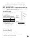
1.6.1. Equivalent Vent Length (EVL)
The longer the run of pipe in your installation, the
greater the restriction in your system.
Always use 4” pipe
Horizontal runs shall not exceed 9 feet.
Never exceed 30 feet of EVL.
To calculate EVL, use the following conversions table:
Qty
Type of pipe
EVL equivalent(ft)
1
90° elbow or “T”
5
1
45° elbow
3
1 ft
Horizontal pipe run
1
1 ft
Vertical pipe run
0.5
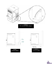
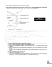
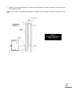
Here is an example on how to calculate the EVL of
your installation. (See Figure 9):
(3 x 4‟ of vertical length = 12‟ x 0.5 = 6 EVL) +
(1 x elbow or "T" = 5 EVL) +
(2 x 1‟ of horizontal length = 2 EVL)
Total EVL = (6 + 5 +2) = 13.
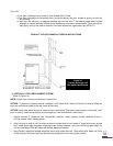
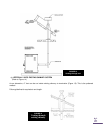
1.6.2. Installation Configurations
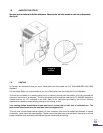
a) HORIZONTALLY THROUGH WALL
(Refer to figures 10,11, or 12)
NOTE: Follow vent chimney manufacturer‟s instructions.
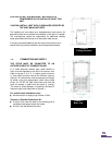
1. Position stove, adhering to clearances shown in Figures 1 & 2.
2. Locate position of hole in wall; directly behind stove exhaust vent (refer to figure 5).
3. Always maintain 3” clearance from combustible materials.
FIGURE 10
Venting through wall