


3
Operation
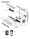
Electric Fireplace Manual Control
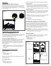
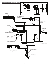
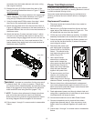
The manual controls for the unit are located in the top, right
corner, on the front of the rebox (Figure 1). A switch is in
the On position when the side with the “ I ”, or “ II ” markings
on it is pushed in.
This three (3) position switch offers the following functions:
(I) Manual mode
When in the “ I ” position, the replace bypasses the built-
in remote control, the ame effect is turned on and the
electrical supply to the heater is controlled manually using
the Low Heat and High Heat Switches (Figure 1-C and D).
(II) Remote mode
The “ II ” position is for operating the unit with the provided
remote control. When in “ II ” position the unit is operated
with the ON and OFF buttons of the remote control.
!
NOTE: Remote control operates main power supply. Heat
must still be controlled by switches on replace.
(O) Off position
All power to all functions are switched off.
Resetting the Temperature Cutoff Switch
Should the replace overheat, an automatic cut out will turn
the heater off and it will not come back on without being
reset. It can be reset by switching the Main Power Switch
(Figure 1-A or B) to the Off (“ O ”) position, and waiting ve
(5) minutes before switching the unit back on.
CAUTION: If you need to continuously reset the heater,
unplug the unit and call Dimplex North America Limited at
1-888-346-7539 for technical support.
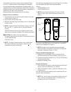
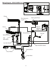
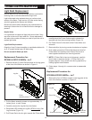
Remote Controls
The following plug-in remote control (Figure 2) is included
with the models and MOD levels specied below:
Used in:
DFI2309 MODs ~ to B•
DFI2310 MOD ~•
Figure 1
A
BCD CD
or
Heat Switches (all models, all MOD levels)
Figure 1-C - Low Heat Switch (“ I ”)
The Low Heat On/Off Switch supplies power to the heater fan
and the heater element. When the switch is in the On (“ I ”)
position the heater operates on Low.
Figure 1-D - High Heat Switch (“ II ”)
The High Heat Switch supplies power to the heater fan and
the heater element, when the switch is in the On (“ II ”)
position the heater operates on High. The C - Low Heat
Switch must also be in the On position for the high heat
setting to operate.
!
NOTE: If Switches C and D are in the Off position, only
the ame effect will turn on when the power switch is
activated.
Main Power Switches (Figure 1-A & B)
A - On/Off Switch
Used in:
DFI2309 MODs ~ to B•
DFI2310 MOD ~•
The two (2) position On/Off Switch supplies power to all the
replace functions.
B - On/Off/On Switch
Used in:
DFI2309 MODs C to D•
DFI2310 MODs A to D•
Figure 2
OPEN
Receiver outlet
Battery
cover
Plug-in
receiver
On button
Off button
Frequency