


13
Power Cord Replacement
If the rebox was operating prior to servicing allow at least
ve (5) minutes for light bulbs and heating element to cool off
to avoid accidental burning of skin.
Disconnect power before attempting any maintenance or
cleaning to reduce the risk of electric shock or damage to
persons.
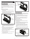
Replacement Procedure:
1. Disconnect power and remove rebox from mantel or
existing replace.
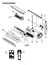
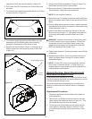
2. Remove four (4) Phillips screws from the top and rear,
upper edge of the rebox as shown in Figure 4-A. This
will release the top cover from the rebox.
3. Lift the top cover of the rebox up carefully - the heater
assembly is attached to the underside of the top cover.
4. Follow the power cord through the rebox chassis and
cut all zip ties that bind the two (2) wires of the power
cord using side cutters.
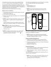
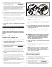
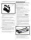
5. Disconnect the power cord
wire which leads to the Main
Power On/Off (or On/Off/On)
Switch. This should be the
only black wire going to this
switch (Figure 10).
6. Use a small Phillips
screwdriver to loosen the
screw which clamps the
other power cord lead into the
terminal block (Figure 10).
Make note of any additional
wires that were clamped
together with power cord.
7. To remove power cord from
chassis, use needle nose
pliers to squeeze sides of
cable clamp and pull through
chassis of rebox, removing clamp and cable.
8. Remove clamp from cable and attach to replacement
cord, leaving approximately eight (8) inches (20 cm) of
slack to wire ends (orientate clamp in same manner with
tapered side facing wire ends).
9. Feed replacement power cord through chassis hole and
using pliers, squeeze sides of cable clamp to push clamp
into sheet metal until snaps in place.
10. Connect terminated wire end to Main Power Switch.
11. Connect crimped wire end to terminal block where
original was removed (step 6). Also ensure any wires
freed in step 6 are clamped together with power cord
wire.
12. Follow steps 1 through 3 in reverse order to reassemble
rebox.
connectors from the heater element and motor, noting
their original locations.
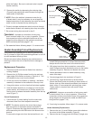
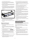
iii) Remove the two (2) Phillips screws from each of the
two (2) mounting brackets as shown in Figure 7. Do not
discard brackets.
iv) Attach the two (2) mounting brackets to the replacement
heater assembly in the same orientation as in Figure 7,
using two (2) Phillips screws removed in step iii.
v) Using the single small Phillips screw from step i, attach
the cutout to the replacement heater assembly.
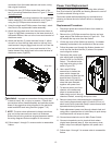
vi) Attach the piggy-back wire from the cutout as shown in
Figure 8: piggy-back connectors to the lower terminal of
the heater element, then on to the inner-most terminal of
the blower motor.
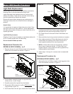
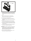
vii) Attach the last two (2) wires removed in step ii: yellow
wire will run from the high heat switch to the top, front-
most terminal; the grey piggy-back wire will run from the
low heat switch to the top, inner-most terminal of the
heater element then piggy-back to the outer terminal of
the blower motor (Figure 9).
Figure 9
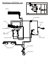
WARNING: Improper re-connection of wiring may result
in electric shock, re, or injury to persons. Ensure that
connections to/from heater assembly and switches match
those of the respective wiring diagram for the particular
model and MOD level being serviced (pages 7-10).
!
NOTE: The wire colors referenced in these instructions
may not be the same as those used in all reboxes.
Ensure that all wiring matches original placement and/or
the wiring diagrams that are supplied in this manual.
viii) Follow steps 1 through 5 in reverse order to reassemble
rebox.
Yellow wire
Grey wire
Figure 10