


17
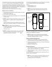
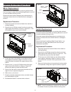
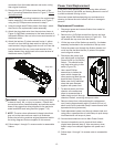
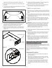
6. The Remote Receiver Board is located on the side panel
just above the entry point for the power cord (Figure 18).
Figure 18
7. Either pinch the clasp to release or cut each of the four
(4) mounting studs (one in each corner of the Receiver
Board) that attach the circuit board to the chassis of the
rebox.
!
NOTE: If mounting studs are cut, ensure they are
replaced by those supplied with replacement board.
8. Clear both ends of mounting studs if cut.
9. Install replacement mounting studs (if necessary) by
pushing them through the sheet metal from the outside of
the rebox.
10. Properly orientate replacement Receiver Board and push
onto mounting studs until all four (4) snap closed.
10. Remove one wire terminal from original Receiver Board
and install onto replacement Receiver Board, matching
its original position.
11. Continue with remaining wire connections, moving one
wire at a time, matching its original position.
WARNING: Improper re-connection of wiring may result
in electric shock, re, or injury to persons. Ensure that
connections to/from circuit board match those of the
respective wiring diagram for the particular model and
MOD level being serviced (pages 7-10).
12. Once all connections are made, follow steps 1 and 2 in
reverse order to reassemble the rebox.
Remote
Receiver
Board
Light Harness Replacement
If the replace was operating prior to servicing allow at least
ve (5) minutes for light bulbs and heating element to cool off
to avoid accidental burning of skin.
Disconnect power before attempting any maintenance or
cleaning to reduce the risk of electric shock or damage to
persons.
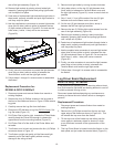
Replacement Procedure for:
DFI2309 & DFI2310 MODs ~ to C
1. Disconnect power and remove rebox from mantel or
existing replace.
2. Remove the two (2) outer Phillips screws on the log grate
at the front of the rebox as shown in Figure 11.
3. Pull the ame assembly drawer out approximately 1½
inches (4 cm), or until it stops.
4. Carefully remove the Log Set from the rebox.
5. Disconnect LED harness to Log Set (DFI2310 only). Set
Log Set aside (Figure 12).
6. Pull Flicker Rod to the far right, towards the Flicker Motor,
carefully bend the Flicker Rod enough to release the
opposite end from the mounting bracket (Figure 12).
7. Pull Flicker Rod off of the shaft of the Flicker Motor and
set aside.
8. Remove both light bulbs by turning counter-clockwise.
9. Lift ame assembly drawer up and out so that metal stop
tabs clear the front edge of the rebox. Pull the drawer
out as far as possible without causing damage to wires
connected at back.
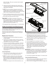
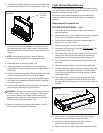
10. Using side cutters, cut the two (2) light harness wires
(blue, white) in between the Terminal Block cover and
the right light socket (Figure 19). Leave as much slack as
possible.
Figure 19
11. Strip ½ inch (1.3 cm) off the ends of the two (2) light
harness wires on the ame motor cover side.
12. Cut the two (2) light harness wires (blue, white) in
between the left and right light sockets.
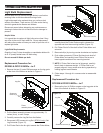
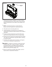
13. Remove the two (2) Phillips light socket screws from the
Terminal Block cover
Light Sockets (2)
Socket screws (2)