


16
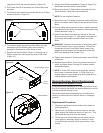
opposite end from the mounting bracket (Figure 12).
5. Pull Flicker Rod off of the shaft of the Flicker Motor and
set aside.
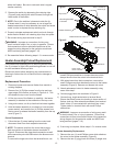
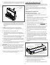
6. Turn rebox onto its back and remove the four (4) Phillips
screws as shown in Figure 15.
9. Using a small Phillips screwdriver, loosen all three (3) of
the left side terminals of the Terminal Block.
10. Remove the three (3) Flicker Motor wire leads from the
Terminal Block, noting their original positions.
!
NOTE: Do not misplace Capacitor.
11. Remove the two (2) Phillips screws that attach the Flicker
Motor to the sheet metal. Remove and discard old Flicker
Motor.
12. Ensure rubber spacer remains in place, properly orientate
replacement Flicker Motor and attach to sheet metal using
screws removed in step 11.
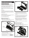
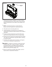
13. Insert Flicker Motor wire leads into left side of Terminal
Block as shown in Figure 17. Wire leads from Capacitor
should align with brown and white wires from Flicker
Motor.
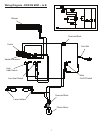
WARNING: Improper re-connection of wiring may result
in electric shock, re, or injury to persons. Ensure that
connections to/from Flicker Motor match those of the
respective wiring diagram for the particular model and
MOD level being serviced (pages 7-10).
14. Tighten down screws of all terminals using a small Phillips
screwdriver.
15. Replace Terminal Block Cover using screws removed in
step 8 and follow steps 1 through 8 in reverse order to
reassemble rebox.
!
NOTE: If Flicker Rod is bent out of alignment, carefully
bend it back to become straight. If Flicker Rod is not
properly aligned, it may cause noise during operation by
rubbing against metal chassis.
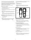
Remote Receiver Board Replacement
DFI2309/2310 MODs C to D
If the replace was operating prior to servicing allow at least
ve (5) minutes for light bulbs and heating element to cool off
to avoid accidental burning of skin.
Disconnect power before attempting any maintenance or
cleaning to reduce the risk of electric shock or damage to
persons.
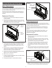
Replacement Procedure:
1. Disconnect power and remove rebox from mantel or
existing replace.
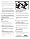
2. Remove four (4) Phillips screws from the top and rear,
upper edge of the rebox as shown in Figure 4-A. This
will release the top cover from the rebox.
3. Tilt the top cover of the rebox up and either prop the
cover against a stationary object or situate it in such
a way that there is access to the upper section of the
rebox.
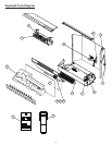
Figure 15
Screws to remove (4)
7. Turn rebox upright and gently pull the ame and light
assembly out of the rebox gently without causing
damage or disconnection to the wiring at back.
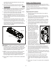
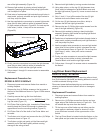
8. Remove the Terminal Block Cover by removing one (1)
Phillips screw from each opposing corner of the cover
(Figure 16).
Figure 16
Terminal Block Cover
Flicker
Motor
Cover
screw
Figure 17
Terminal Block
Capacitor