


11
Mirror Replacement
If the rebox was operating prior to servicing allow at least
ve (5) minutes for light bulbs and heating element to cool off
to avoid accidental burning of skin.
Disconnect power before attempting any maintenance or
cleaning to reduce the risk of electric shock or damage to
persons.
Replacement Procedure
1. Disconnect power and remove rebox from mantel or
existing replace.
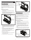
2. Remove four (4) Phillips screws from the top and rear,
upper edge of the rebox as shown in Figure 4-A. This
will release the top cover from the rebox.
Switch Replacement
If the rebox was operating prior to servicing allow at least
ve (5) minutes for light bulbs and heating element to cool off
to avoid accidental burning of skin.
Disconnect power before attempting any maintenance or
cleaning to reduce the risk of electric shock or damage to
persons.
Each of the three (3) switches (Main Power Switch, Low
Heat Switch and High Heat Switch) will have the same
replacement procedure.
Replacement Procedure:
1. Disconnect power and remove rebox from mantel or
existing replace.
2. Remove four (4) Phillips screws from the top and rear,
upper edge of the rebox as shown in Figure 4-A. This
will release the top cover from the rebox.
3. Tilt the top cover of the rebox up and either prop the
cover against a stationary object or situate it in such
a way that there is access to the upper section of the
rebox.
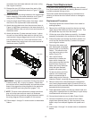
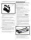
4. Remove all wiring clips and connections from the switch
to be replaced, noting their original locations (Figure 6).
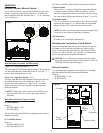
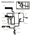
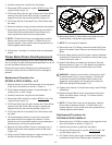
Figure 4
Universal Replacement Procedures
3. Tilt the top cover of the rebox up and either prop the
cover against a stationary object or situate it in such
a way that there is access to the upper section of the
rebox.
4. Remove one (1) or two (2) Phillips screws from each
upper corner of the rebox as shown in Figure 4-B.
Quantity will differ by model and MOD level.
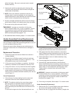
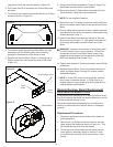
5. Gently push the switch control panel inwards until top
edge of mirror is exposed (Figure 5).
6. Slide mirror up to remove.
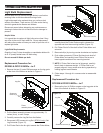
7. Properly orientate replacement mirror and slide it down
into place behind Log Set.
8. Re-assemble rebox in reverse order as above.
B. Step 3
screws to
remove
A. Step 2
screws to
remove
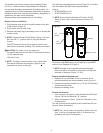
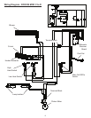
Figure 5
Mirror
Log set
Switch
control panel
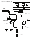
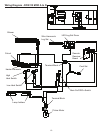
Figure 6
Wire
connection
terminals
High Heat switch
Low Heat switch
Main
power switch
Retainer clips
!
NOTE: It may be necessary to remove all wire clips and/
or switches in order to provide sufcient working room