


12
a small Phillips screwdriver to loosen the screw which
clamps the wire from the cutout to the terminal block.
ii) With wires loose from their connections, remove the
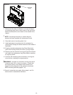
small Phillips screw that attaches the cutout to the heater
assembly (Figure 8). Remove and discard old cutout.
iii) Attach replacement cutout to heater assembly using
screw from step ii.
iv) Connect piggy-back wire as shown in Figure 8.
v) Connect long, single-ended wire to terminal block.
Ensure that black power wire leading to lower section of
rebox (and any other wires disconnected from terminal
block in step i) is connected with wire lead from cutout.
Tighten down on terminal block with small Phillips
screwdriver.
WARNING: Improper re-connection of wiring may result
in electric shock, re, or injury to persons. Ensure that
connections to/from cutout match those of the respective
wiring diagram for the particular model and MOD level
being serviced (pages 7-10).
vi) If servicing is complete, follow steps 1-5 in reverse order.
Heater Assembly Replacement
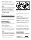
i) Remove the one (1) small Phillips screw which attaches
the cutout to the heater assembly (Figure 8).
ii) Remove the two (2) piggy-back and three (3) single wire
within the rebox. Be sure to note each wire’s original
location carefully.
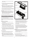
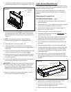
5. Remove the switch by depressing the retaining clips
(Figure 6) and pushing the switch forward, through the
sheet metal of the rebox.
!
NOTE: Due to the switches’ placement under the lip
of sheet metal, it may be necessary to use a large at-
headed screwdriver to slide between the switch and sheet
metal in order to depress the top retaining clip.
6. Properly orientate replacement switch and push through
sheet metal of rebox until retaining clips snap into place.
7. Re-connect wiring clips removed in step 5.
WARNING: Improper re-connection of wiring may
result in electric shock, re, or injury to persons. Ensure
that connections to/from switches match those of the
respective wiring diagram for the particular model and
MOD level being serviced (pages 7-10).
9. Re-assemble rebox following steps 1-3 in reverse order.
Heater Assembly/Cutout Replacement
If the rebox was operating prior to servicing allow at least
ve (5) minutes for light bulbs and heating element to cool off
to avoid accidental burning of skin.
Disconnect power before attempting any maintenance or
cleaning to reduce the risk of electric shock or damage to
persons.
Replacement Procedure
1. Disconnect power and remove rebox from mantel or
existing replace.
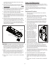
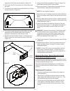
2. Remove four (4) Phillips screws from the top and rear,
upper edge of the rebox as shown in Figure 4-A. This
will release the top cover from the rebox.
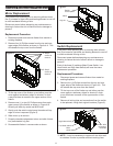
3. Lift the top cover of the rebox up carefully - the heater
assembly is attached to the underside of the top cover.
4. Using side cutters, cut all zip ties that bind wires together
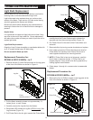
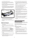
5. Hold the heater assembly in one hand (or have another
person assist), and remove four (4) Phillips screws from
the top cover to release the heater assembly from the top
cover (Figure 7).
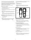
Cutout Replacement
i) Follow the two (2) wires leading from the cutout and
disconnect them from their respective terminals.
!
NOTE: The shorter wire from the cutout has a piggy-
back connection at the heater element as shown in
Figure 8. Disconnect the piggy-back connection as well
as the secondary wire that connects to the blower motor
terminal.
To remove the longer wire from the terminal block, use
Figure 7
Step 5 screws to
remove (4)
Top cover
Heater elements
Heater blower & motor
Mounting brackets
& screws
Figure 8
Cutout screw
Heater
elements
Blower motor
Terminal block
Upper, inside
corner of rebox