


106918-01B
For more information, visit www.desatech.com
For more information, visit www.desatech.com
12
VENTING INSTALLATION
Installation For Horizontal Termination (Cont.)
Installation For Vertical Termination
VENTING INSTALLATION
Continued
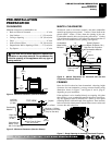
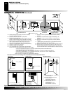
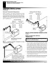
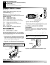
Figure 21 - Horizontal Termination Configuration for Rigid
Venting Using One 90° Elbow
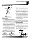
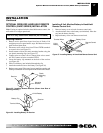
Figure 22 - Horizontal Termination Using Flexible Venting
Horizontal Venting
Vertical (V) Horizontal (H)
49.5" min. 15" max.
(45° elbow, 1' vertical pipe, 90° elbow)
61.5" min. 34" max.
73.5" min. 58" max.
85.5" min. 10' max.
102.5" min. 20' max.
Horizontal Venting
See information in Figure 21 for
Vertical(V) and Horizontal(H) maxi-
mums and minimums. The same
amounts apply for flexible venting.
FGFVK Vent Kit Shown
Horizontal Termination Configurations
Figures 21 through 23 show different configurations for venting
with horizontal termination. Each figure includes a chart with
vertical minimum/maximum and horizontal maximum dimensions
which must be met. All connections must be sealed with high
temperature silicone sealant as specified in the second warning
statement on page 9. All horizontal terminations require 1/4" rise
per 12" of horizontal run.
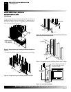
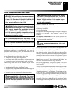
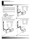
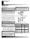
Note:
The PA-47-6 Pipe Adaptor
Must Be Attached Prior to the
45° Starter Elbow
45° Starter
Elbow Required
Venting with Two 90° Elbows
Vertical (V) Horizontal (H
1
) +
Horizontal (H
2
)
5' min. 4' max.
6' min. 8' max.
7' min. 10' max.
8' min. 15' max.
20' max. 20' max.
Figure 23 - Horizontal Termination Configuration for Rigid
Venting Using Two 90° Elbows with Termination at 90° with
Fireplace
45° Starter
Elbow
Required
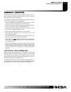
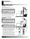
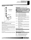
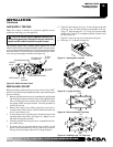
1. Determine the route your vertical venting will take. If ceiling
joists, roof rafters, or other framing will obstruct the venting
system, consider an offset (see Figure 24, page 13) to avoid
cutting loadbearing members.
Note:
Pay special attention to
these installation instructions for required clearances (air space)
to combustibles when passing through ceilings, walls, roofs,
enclosures, attic rafters, etc. Do not pack air spaces with insu-
lation. Also note maximum vertical rise of the venting system
and any maximum horizontal offset limitations. Offsets must
fall within the parameters shown in Figure 13 on page 8.
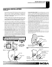
2. Set the fireplace in desired location. Drop a plumb line down
from the ceiling to the position of the fireplace exit flue. Mark
the center point where the vent will penetrate the ceiling. Drill
a small locating hole at this point.
Drop a plumb line from the inside of the roof to the locating
hole in the ceiling. Mark the center point where the vent will
penetrate the roof. Drill a small locating hole at this point.
INSTALLATION FOR VERTICAL
TERMINATION
NOTICE: Use rigid pipe only. Flex venting is not to be
used with a vertical termination.