


106918-01B
For more information, visit www.desatech.com
For more information, visit www.desatech.com
14
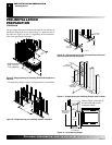
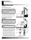
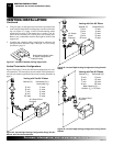
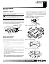
Figure 27 - Installed Cathedral Ceiling Support Box
Nonhardening Mastic under
all edges of support box
before nailing
4. Using tin snips, cut the support box from the top corners down
to the roofline and fold the resulting flaps over the roof sheath-
ing (see Figure 27). Apply a bead of non-hardening mastic
around the top edges of the support box to make a seal be-
tween the box and the roof. Nail in place with roofing nails.
Remove any combustible material that might be inside of the
support box.
5. Complete the cathedral ceiling installation by following the
same procedures outlined in steps 2 through 7 for Flat Ceiling
Installation, page 13
.
VENTING INSTALLATION
Continued
VENTING INSTALLATION
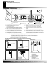
Installation For Vertical Termination (Cont.)
Vertical Termination Configurations
Figures 28 through 31 show four different configurations for verti-
cal termination. All connections must be sealed with high tempera-
ture silicone sealant as specified in the second warning statement on
page 9.
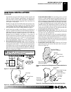
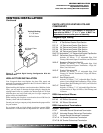
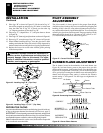
Venting with Two 90° Elbows
Vertical (V) Horizontal (H
1
) +
Horizontal (H
2
)
5' min. 2' max.
6' min. 4' max.
7' min. 6' max.
8' min. 8' max.
20' max. 8' max.
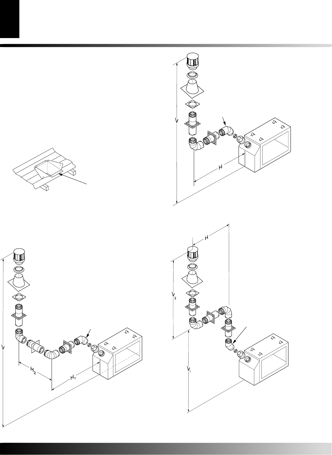
Figure 28 - Vertical Rigid Venting Configuration Using Two 90°
Elbows with Two Horizontal Runs
45° Starter Elbow
Required
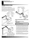
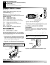
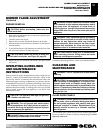
Venting with One 90° Elbow
Vertical (V) Horizontal (H)
5' min. 2' max.
6' min. 4' max.
7' min. 6' max.
8' min. 8' max.
20' max. 8' max.
Figure 29 - Vertical Rigid Venting Configuration Using One 90°
Elbow
45° Starter
Elbow
Required
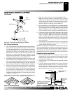
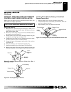
Venting with Two 90° Elbows
Vertical (V
1
) Horizontal (H)
5' min. 6' max.
6' min. 12' max.
7' min. 18' max.
8' min. 20' max.
Note:
Vertical (V
1
) +
Vertical (V
2
) = 20' max.
Figure 30 - Vertical Rigid Venting Configuration Using Two 90°
Elbows
45° Starter Elbow
Required