


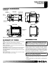
106918-01B
For more information, visit www.desatech.com
For more information, visit www.desatech.com
11
11
VENTING INSTALLATION
Installation For Horizontal Termination (Cont.)
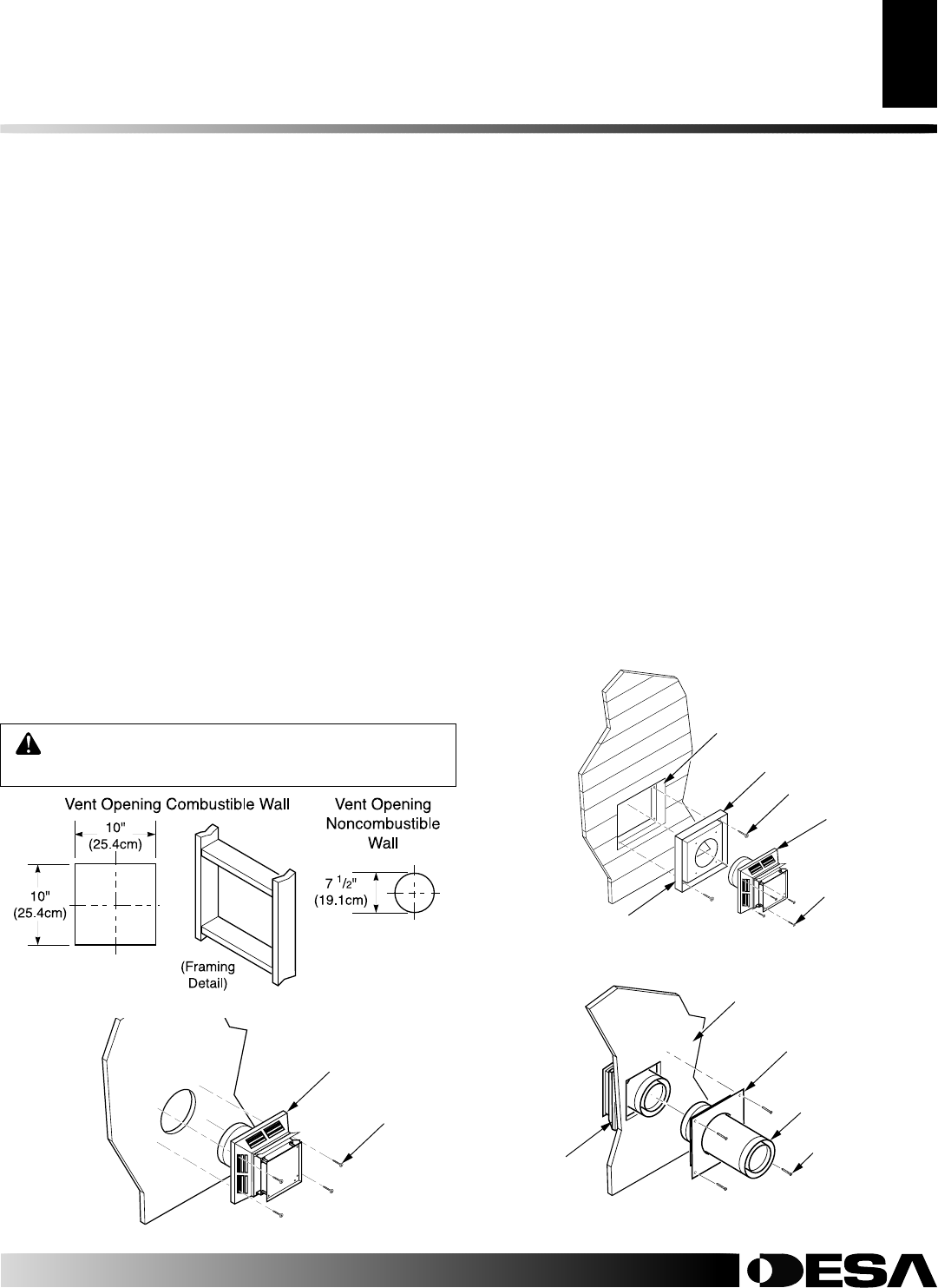
WARNING: Do not recess vent termination in to
any wall. This will cause a fire hazard.
VENTING INSTALLATION
Continued
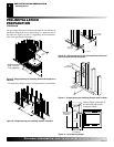
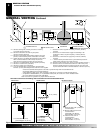
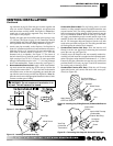
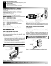
Figure 17 - Vent Opening Requirements
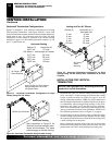
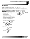
Figure 18 - Installing Horizontal Vent Cap
Wood Screw
Vent Cap
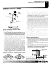
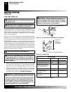
Figure 19 - Installing Vinyl Siding Standoff (Combustible Exterior
Wall)
Cut Vinyl Siding
Away to Fit Standoff
Wood Screw
Bolt
Standoff
Vent Cap
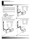
Apply Mastic
to All Four Sides
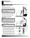
Vent Cap
(Horizontal
Termination)
Interior Wall
Surface
Interior Wall Firestop
(Combustible
Exterior Wall Only)
Horizontal
Vent Pipe
Figure 20 - Connecting Vent Cap with Horizontal Vent Pipe
Screw
ing statement on page 9.) Push the pipe sections together and
twist one section clockwise approximately one-quarter turn
until the sections are fully locked. See Figure 16.
Note:
Hori-
zontal runs of vent must be supported every three feet. Use
wall straps for this purpose.
Flexible vent pipe must be installed with spacer springs every
12" (30.5cm). See Figure 16, page 10. All connections must be
clamped tightly and sealed with high temperature silicone seal-
ant as specified in the second warning statement on page 9.
3. Attach vent pipe assembly to the fireplace. Set fireplace in
front of it’s permanent location to insure minimum clearances.
Mark the wall for a 10" square hole (for noncombustible ma-
terial such as masonry block or concrete, a 7
1
/2" (19.1cm)
diameter hole is acceptable). See Figure 17. The center of
the hole should line up with the center-line of the horizontal
rigid vent pipe. Cut a 10"x10" (25.4cm x 25.4cm) square hole
through combustible exterior wall (7
1
/2" [19.1cm] diameter
hole if noncombustible). Frame as necessary (see Figure 17).
4. Noncombustible Exterior Wall: Apply a bead of non-harden-
ing mastic around the outside edge of the vent cap. Position the
vent cap in the center of the 7
1
/2" (19.1cm) hole on the exterior
wall with the arrow on the vent cap pointing up. Attach the vent
cap with four wood screws provided (see Figure 18).
Note
: Re-
place the wood screws with appropriate fasteners for stucco, brick,
concrete, or other types of siding.
Combustible Exterior Wall: For vinyl siding, stucco, or wood
exteriors, a siding standoff must be installed between the vent
cap and exterior wall. The siding standoff prevents excessive
heat from damaging siding materials. Siding materials must be
cut to accommodate standoff. Bolt the vent cap to the stand-
off. Apply non-hardening mastic around outside edge of the
standoff. Position the standoff/cap assembly in the center of
the 10" (25.4cm)square hole and attach to exterior wall with
wood screws provided (see Figure 19). The siding standoff must
sit flush against the exterior fascia material.
5.
Combustible Exterior Wall Only: Slide the interior wall
firestop over the vent pipe before connecting the horizontal
run to the vent cap (see Figure 20).
6. Carefully move the fireplace with vent assembly attached to-
ward the wall and insert the vent pipe into the horizontal termi-
nation. The pipe overlap should be a minimum of 1
1
/4" (3.2cm).
Fasten all vent pipe connections (except vent cap) with screws
provided. Refer to Framing on pages 5 and 6 for instructions
on securing unit to framing or floor.
7. Combustible Exterior Wall Only: Slide the wall firestop
against the interior wall surface and attach with screws pro-
vided (see Figure 20).