


106918-01B
For more information, visit www.desatech.com
For more information, visit www.desatech.com
16
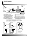
PARTS LISTS FOR VENTING KITS AND
COMPONENTS
(Cont.)
DESA International Venting Accessories
Number Description
SC-47 Galvanized Storm Collar
WF-47 Galvanized Wall Firestop
RF-47-6 Galvanized Roof Flashing, 0 to 6/12 Pitch
RF-47-12 Galvanized Roof Flashing, 6/12 to 12/12 Pitch
VR-47 Galvanized Vertical Restrictor
S-47 Galvanized Combustible Siding Standoff
WS-47 Wall Strap
FP-47 Firestop Plate
PA-47-6 Galvanized 6" Pipe Adaptor (Required)
VENTING INSTALLATION
Parts Lists For Venting Kits And Components (Cont.)
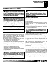
INSTALLATION
Wall Switch Installation
Electrical Hookup For Blower Accessory
WARNING: Do not wire remote wall switch to main
power supply (Standard 120v household current).
INSTALLATION
WALL SWITCH INSTALLATION
Since the VDDVF36 series models use a valve that operates on
millivolt current generated by the pilot, a wall switch (not included)
may be used to activate the gas control valve without the use of
normal household electricity.
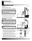
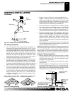
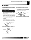
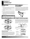
1. To remove the louvers, simultaneously pull both top end spring
latches towards the center of the appliance until they are dis-
engaged from locating holes. Repeat for bottom end spring
latches and pull outward. Reverse the procedure to install lou-
vers back onto the appliance (see Figure 32).
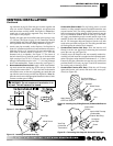
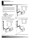
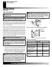
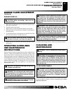
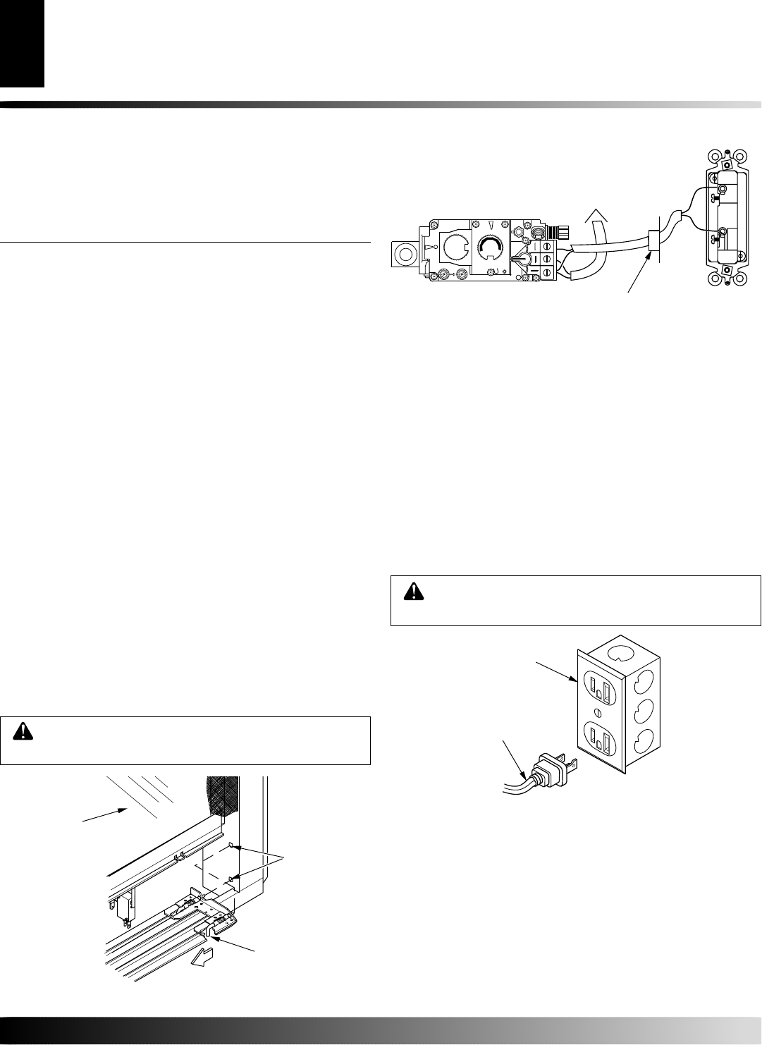
2. Connect the 18 ga. wires from wall switch (not included) to
the gas control valve and microswitch, as shown in Figure 33.
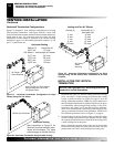
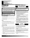
ELECTRICAL HOOKUP FOR BLOWER
ACCESSORY
Before blower accessory can be operated, it must be properly
connected to a standard 120 VAC power source. Refer to Wiring
Diagram on page 28.
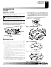
An outlet box with two receptacles has been supplied for your
convenience, located on the lower left side of the appliance (see
Figure 34). An optional remote control may be installed at any time.
CAUTION: Due to high temperatures, make sure
no wires are touching the bottom of the firebox.
Figure 32 - Removing Louver
Glass
Locating
Holes
Spring
Latch
Figure 33 - Wall Switch Wiring Diagram
O
F
F
P
I
L
O
T
O
N
L
O
H
I
P
I
L
O
T
EA
16AI
7
TPTH TP TH
Wall Switch
(Supplied)
Route Millivolt Wires
(Supplied) Through Gas
Line Conduit Sleeve
To Thermopile
(Back View)
Note:
If any of the original wire supplied must be replaced, use type
18 AWG-105 degree C (25 feet length MAXIMUM) or equivalent.
Figure 34 - Connecting Blower Accessory to Power Supply
For Optional
Fan Kit
From Blower
Assembly
VENTING INSTALLATION
Continued