


106918-01B
For more information, visit www.desatech.com
For more information, visit www.desatech.com
13
13
VENTING INSTALLATION
Installation For Vertical Termination (Cont.)
VENTING INSTALLATION
Continued
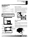
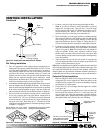
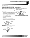
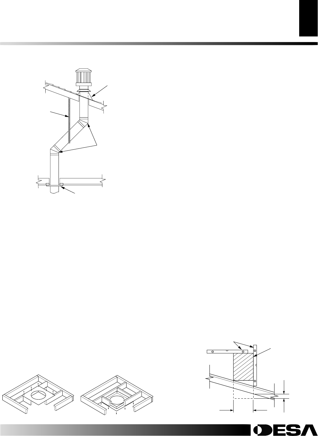
4. Connect a section of pipe and extend up through the hole.
Note:
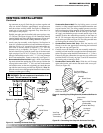
If an offset is needed to avoid obstructions, you must
support the vent pipe every 3 feet (91.4cm). Use wall straps
for this purpose (see Figure 24). Whenever possible, use 45°
elbows instead of 90° elbows. The 45° elbow offers less re-
striction to the flow of the flue gases and intake air.
5. Place the flashing over the pipe section(s) extending through
the roof. Secure the base of the flashing to the roof and framing
with roofing nails. Be sure roofing material overlaps the top
edge of the flashing as shown in Figure 24. There must be a 1"
(2.5cm) clearance from the vent pipe to combustible materials.
6. Continue to add pipe sections until the height of the vent cap
meets the minimum building code requirements described in
Figure 13 on page 8.
Note
: You must increase vent height for
steep roof pitches. Nearby trees, adjoining rooflines, steep
pitched roofs, and other similar factors may cause poor draft
or down-drafting in high winds. Increasing the vent height may
solve this problem.
7. Twist-lock the vent cap onto the last section of vent pipe and
seal with high temperature silicone sealant as specified in the
second warning statement on page 9.
Note:
If the vent pipe passes through any occupied areas above the first
floor, including storage spaces and closets, you must enclose pipe. You
may frame and sheetrock the enclosure with standard construction
material. Make sure and meet the minimum allowable clearances to
combustibles. Do not fill any of the required air spaces with insulation.
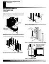
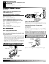
Cathedral Ceiling Installation
1. Remove shingles or other roof covering as necessary to cut the
rectangular hole for the support box. Mark the outline of the
cathedral ceiling support box on the roof sheathing using the
locating hole as a center point.
2. Cut the hole 1/8" (0.3cm) larger than the support box outline
(see Figure 26).
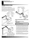
3. Lower the support box through the hole in the roof until the
bottom of the box extends at least 2" (5.1cm) below the ceil-
ing (see Figure 26). Align the support box vertically and hori-
zontally using a level. Temporarily tack the support box in place
through the inside walls and into the roof sheathing.
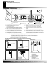
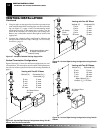
Flat Ceiling Installation
1. Cut a 10" square hole in the ceiling using the locating hole as a
center point. The opening should be framed to 10"x10" (25.4cm
x 25.4cm) inside dimensions, as shown in Figure 17 on page 11
using framing lumber the same size as the ceiling joists. If the
area above the ceiling is an insulated ceiling or a room, nail
firestop from the top side. This prevents loose insulation from
falling into the required clearance space. Otherwise, install
firestop below the framed hole. The firestop should be installed
with no less than three nails per side (see Figure 25).
2. Assemble the desired lengths of pipe and elbows necessary to reach
from the fireplace flue up through the firestop. All connections
must be sealed with high temperature silicone sealant as specified
in the second warning statement on page 9. Be sure all pipe and
elbow connections are fully twist-locked (see Figure 16, page 10).
3. Cut a hole in the roof using the locating hole as a center point.
(Cover any exposed open vent pipes before cutting hole in
roof.) The 10"x10" (25.4cm x 25.4cm) hole must be measured
on the horizontal; actual length may be larger depending on
the pitch of the roof. There must be a 1" clearance from the
vent pipe to combustible materials. Frame the opening as shown
in Figure 17 on page 11.
Figure 24 - Offset with Wall Strap and 45° Elbows
45° Elbow
Wall Strap
Roof
Flashing
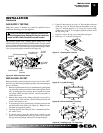
Ceiling Firestop
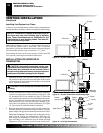
Figure 25 - Installing Firestop
If area above is not a room, install
firestop below framed hole.
If area above is a room, install
firestop above framed hole.
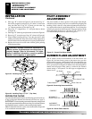
Figure 26 - Cathedral Ceiling Support Box Installation
Cut hole 1/8" (0.3cm) larger
than support box when
projected onto roofline
2" (5.1cm)
minimum
below
finished
ceiling
Level
Cathedral ceiling
support box