


4
106442
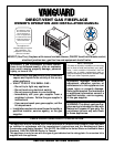
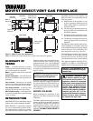
MDVFST DIRECT-VENT GAS FIREPLACE
®
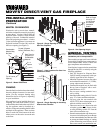
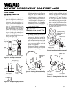
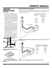
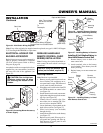
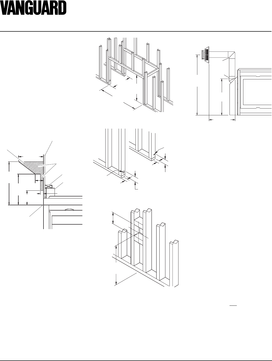
FRAMING
Once the final location has been determined,
observing height clearances for vent termi-
nation, you may construct framing using
dimensions shown in Figure 6, depending
on your installation.
If the appliance is to be installed directly on
carpeting, tile (other than ceramic), or any
combustible material other than wood floor-
ing, the appliance must be installed on a
metal or wood panel extending the full width
and depth of the appliance. There are three
holes on each side of the bottom of the unit
where screws can be used to secure the unit
to the floor.
39
3
/4"
(1010mm)
Min.
43
1
/4"
(1098mm)
23
5
/
8
"
(600mm)
Figure 6 - Rough Opening for Installing
See Thru Fireplace
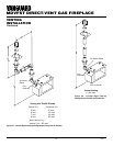
3" (76mm)
1" (25mm)
Dia. Hole
3"
(76mm)
2" (51mm)
Dia. Hole
1"
(25mm)
2"
(51mm)
Height
Depends On
Installation
10"
(254mm)
Square Min.
Figure 7 - Hole Locations For Gas Line
and Electric Wires
Figure 8 - Rough Opening for Installing
Exterior Vent Terminal
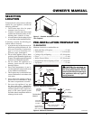
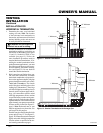
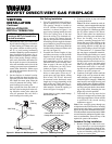
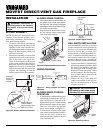
MANTEL CLEARANCES
Woodwork, such as wood trims, mantels,
and other combustible materials projecting
no more than 1
1
/2 inches (3.8cm) shall not
be placed within 7 inches (17.8cm) from the
opening of the unit. Combustible material
above and projecting more than 1
1
/2 inches
(3.8cm) from the appliance’s face must not
be placed less than 15 inches (38.1cm) from
the louver opening (see Figure 5).
Figure 5 - Mantel Clearances
12"
(305mm)
Min.
21"
(533mm)
Min.
15"
(381mm)
Min.
4"
(102mm)
Min.
7" (178mm)
Min.
1
1
/
2
" (38mm)
Min.
UNIT
Spacer
2 x 4
Combustible
Material May
Be Used
Drywall (Gypsum
Board, Sheetrock, Etc.)
Safe Zone for
Projection of
Combustible
Material
Note:
Terminations are not designed for
installation prior to transportation.
These models are approved for use with both
flex and rigid Vanguard vent components as
well as Simpson Dura-Vent 6
5
/8" direct-vent
pipe components and terminations.
Your fireplace is approved to be vented either
through the side wall, or vertically using the
following guidelines:
• Only use Vanguard or Simpson Dura-
Vent GS venting components or kits spe-
cifically approved for this fireplace.
• Minimum clearance between vent pipes
and combustible materials is 1" (25 mm),
except where stated otherwise.
• Combustible material may be flush with
the top front of fireplace with a maxi-
mum thickness of 3/4".
• Do not recess venting terminals into a
wall or siding.
• Install horizontal venting with a 1/4" rise for
every 12" of run toward the termination.
• You may paint the vent terminal with
450°F (232°C) heat-resistant paint to co-
ordinate with the exterior finish.
• There must not be any obstruction such
as bushes, garden sheds, fences, decks,
or utility buildings within 24" from the
front of the termination cap.
• Do not locate termination cap where exces-
sive snow or ice build up may occur. Be sure
to clear vent termination area after snow falls
to prevent accidental blockage of venting
system. When using snow blowers, do not
direct snow towards vent termination area.
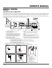
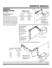
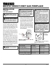
GENERAL VENTING
Vertical Height
Depends on
Installation
26
3
/8"
(670mm)
Horizontal
Length Depends
on Installation
90
o
Elbow
45
o
Elbow
Refer to Pages
9 through 12
for Horizontal
and Vertical
Installation
Details
Figure 9 - Vent Opening Height
Top of Louver
Opening
PRE-INSTALLATION
PREPARATION
Continued