


3
106442
OWNER’S MANUAL
To determine the safest and most efficient
location for your appliance, consider the
following guidelines:
1. The location must allow for proper
clearances (see Clearances).
2. Consider a location where heat output
would not be affected by drafts, air con-
ditioning ducts, windows, or doors.
3. A location that avoids the cutting of joists
or roof rafters makes installation easier.
In selecting a location, the following pre-
cautions must be observed:
1. A projection may be ideal for a new ad-
dition on an existing finished wall. See
Horizontal Termination Configuration,
page 9, or Vertical Termination Con-
figuration, pages 10 through 12.
2. Do not locate appliance close to where
gasoline or other flammable liquids may
be stored. The appliance must be kept clear
and free from combustible materials.
3. Do not connect this appliance to a
chimney system used for solid fuel
burning fireplace.
4. Due to high temperatures, do not lo-
cate this appliance in high traffic areas
or near furniture and draperies.
5. This fireplace may be installed in bed-
rooms or bathrooms in accordance with
local codes.
6. Never obstruct the openings of the ap-
pliance or flow of ventilation air. Keep
the control compartments accessible.
7. Do not use this appliance if any part
has been under water. Immediately
contact a local service technician to ex-
amine the appliance and to replace any
part(s) of the control ignition system
and other related components that have
submerged under water.
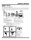
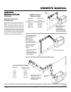
SELECTING
LOCATION
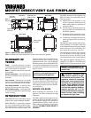
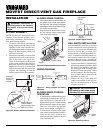
Figure 2 - Possible Installation of See-
Thru Fireplace
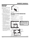
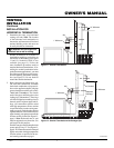
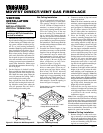
CLEARANCES
Minimum clearances to combustibles are:
• Back and Sides of Fireplace:................................. 0" min.
• Vent Surfaces: .......................................... 1" (2.5cm) min.
• Ceiling to Top of Opening: ..................... 36" (91cm) min.
• Floor: ..................................................................... 0" min.
• Wall to Front of Glass: ............................ 36" (91cm) min.
• Perpendicular Wall to Opening of Unit:...... 2" (5cm) min.
• Top Spacer: ........................................................... 0" min.
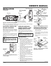
Figure 3 - Minimum Clearances
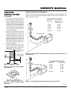
Figure 4 - Minimum Clearances
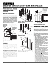
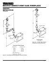
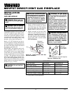
PRE-INSTALLATION PREPARATION
CEILING
WALL
36"
(914mm)
Min.
36"
(914mm)
Min.
0" Floor
0"
36"
(914mm)
2" (51mm)
Wall In Front Of Glass
36" (91cm) Min.
Perpendicular
Wall 2" (51mm)
Min. From Opening
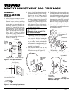
Right Side
Surround
(0" Min.)
Left Side
Surround
(0" Min.)
TOP VIEW
Combustible
Material
Drywall
2 x 4 Stud
Minimum 1"
Clearance from
Side
CAUTION: Do not block re-
quired air spaces with insula-
tion or any other material. Do not
obstruct the effective opening of
the appliance with any type of
facing material.
Continued
Top Spacers