


14
106442
MDVFST DIRECT-VENT GAS FIREPLACE
®
INSTALLATION
BLOWER ASSEMBLY
NOTE:
The blower is preinstalled in this
fireplace. Verify blower assembly place-
ment during installation. The blower may
have shifted during shipping.
1. To remove lower louver, pull both top
spring latches toward the center of the
appliance at the same time until they
are disengaged from the locating holes.
Repeat for bottom spring latches and
pull louver outward.
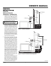
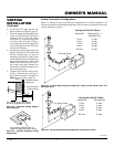
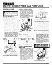
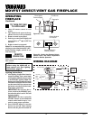
2. Place blower assembly so it rests flush
against the inside wall on the flue exit
side of the firebox (see Figure 29).
There are four magnets on the bottom
of the blower assembly that will keep
the blower in place on firebox bottom.
Note:
If the blower kit is not installed
flush against the inside side wall of the
fireplace, the circulating air from the
blower system will not flow properly.
WARNING: Disconnect all
electrical power to the fireplace.
Be careful of burrs and sharp
edges.
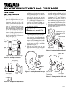
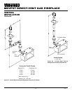
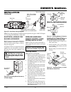
BLOWER SPEED CONTROL
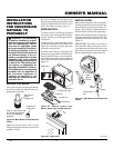
1. Place speed control switch assembly on
the bottom of the inside of the firebox
(see Figure 30). The assembly is equipped
with magnets on the left and right to prop-
erly anchor it to the firebox.
2. Plug blower with speed control assem-
bly into a power source. Keep hands
clear of fan when running.
Figure 29 - Blower Assembly Placement
Blower
Assembly
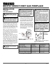
WIRING DIAGRAM
Figure 30 - Blower Speed Control Location
Glass
Speed Control
Spring
Latch
BLOWER
SPEED
CONTROL
BLOWER
ASSEMBLY
BLK (16 ga.)
BLK (16 ga.)
Wire Connectors
3 Places
Figure 31 - Wiring Diagram for Blower
Assembly
Magnet
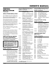
High Speed
ON/OFF
Low
Speed
Magnets
1/4 Revolution
Figure 32 - Blower Speed Control
Blower Center to
Firebox Bottom
Center Along Inside
Wall by Flue Exit
Peninsula
or See-Thru
Fireplace
Installed
Flue
Exit
Inside
Wall
WARNING: Do not wire remote
wall switch to main power supply
(Standard 120v household current).
WALL SWITCH INSTALLATION
Since the MDVFST model uses a valve that
operates on millivolt current generated by
the pilot, a wall switch (not included) may
be used to activate the gas control valve
without the use of normal household elec-
tricity. A hand-held, ON/OFF remote con-
trol is standard with this unit. Wall switch is
optional. If the wall switch is installed, the
hand-held, ON/OFF remote cannot be used.
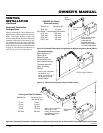
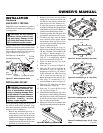
1. To remove the louvers, simultaneously
pull both top end spring latches towards
the center of the appliance until they
are disengaged from locating holes.
Repeat for bottom end spring latches
and pull outward. Reverse the proce-
dure to install louvers back onto the
appliance (see Figure 33).
2. Connect the 18 ga. wires from wall
switch (not included) to the gas con-
trol valve and microswitch, as shown
in Figure 34, page 15.
Figure 33 - Removing Louver
Glass
Locating
Holes
Spring
Latch
BLOWER SPEED CONTROL
OPERATION
1. To operate blower, turn the blower speed
control knob clockwise to the “ON” po-
sition (see Figure 32). This will be the
highest blower speed. Continue turning
knob clockwise to reduce blower speed.
Turn knob only within the specified
range (1/4 revolution, see Figure 32).
2. To turn blower off, turn blower speed
control knob counterclockwise until it
clicks into the “OFF” position. You
must turn until knob clicks for the unit
to be completely off.