


15
106442
OWNER’S MANUAL
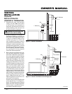
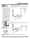
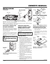
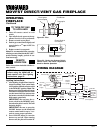
Figure 34 - Wall Switch Wiring Diagram
WIRELESS HAND-HELD
REMOTE CONTROL (GHRC
SERIES) INSTALLATION
Note:
If using the wireless hand-held re-
mote control, the wall switch is no longer
operational.
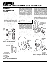
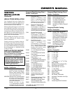
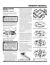
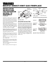
Figure 36 - Installing Remote Receiver
(Shown from Rear of Mounting Bracket)
Figure 37 - Installing Battery in Receiver
INSTALLATION
Continued
O
F
F
P
I
L
O
T
O
N
P
I
L
O
T
EA
16AI
7
TPTH TP TH
Optional Wall Switch
Route Millivolt Wires (Supplied)
Through Gas Line Conduit Sleeve
To
Thermopile
(Back View)
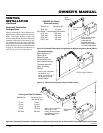
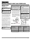
ELECTRICAL HOOKUP FOR
BLOWER ACCESSORY
Before blower accessory can be operated, it
must be properly connected to a standard
120 VAC power source. Refer to Wiring
Diagram on page 20.
An outlet box with two receptacles has been
supplied for your convenience, located on
the lower left side of the appliance (see
Figure 35).
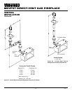
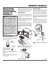
Figure 35 - Connecting Blower Accessory
to Power Supply
From Blower
Assembly
Note:
If any of the original wire supplied must be replaced, use type 18 AWG-105 degree
C (25 feet length MAXIMUM) or equivalent.
CAUTION: Due to high tem-
peratures, make sure no wires
are touching the bottom of the
firebox.
NOTICE: Only use alkaline bat-
teries (not included, requires 2).
Installing Receiver
Note:
Receiver is preinstalled.
1. Remove access panel from lower front
face of firebox. Lift straight up on ac-
cess panel until it stops. Pull bottom of
access panel forward, then down.
2. Disconnect wall switch wires from TH
and TPTH terminals on control valve
(see Figure 34).
3. Install remote receiver unit onto mount-
ing bracket using the two plastic mount-
ing clips (see Figure 36).
4. Connect wires to control valve. Con-
nect white wire to terminal TH. Con-
nect red wire to terminal TP/TH.
5. Locate the battery clip mounted on the
back of the receiver (see Figure 37).
6. Slide 9-volt battery (not included)
through the clip.
7. Attach the terminal wires to the battery
(see Figure 37).
8. Replace access panel. Place top of ac-
cess panel into opening and slide up.
Push bottom of access panel in and
slide down to install.
Battery Clip
9-Volt Battery
Receiver
Terminal
Wires
Receiver
Mounting
Bracket
Plastic
Mounting
Clips
Note:
This unit does
not have a HI/LOW
feature
Continued
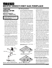
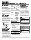
Installing 9-Volt Alkaline Battery in
Hand-Held Remote Control Unit
1. Remove battery cover on back of re-
mote control unit.
2. Attach terminal wires to the battery
(not included). Place battery into the
battery housing.
3. Replace battery cover onto remote con-
trol unit.
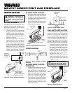
Figure 38 - Installing Battery in Hand-
Held Remote Control Unit
Battery
Cover
9-Volt
Battery
Terminal
Wires
Remote
Control Unit
Battery
Housing
Gas Valve