


111167-01C
14
For more information, visit www.desatech.com
For more information, visit www.desatech.com
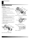
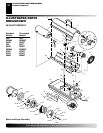
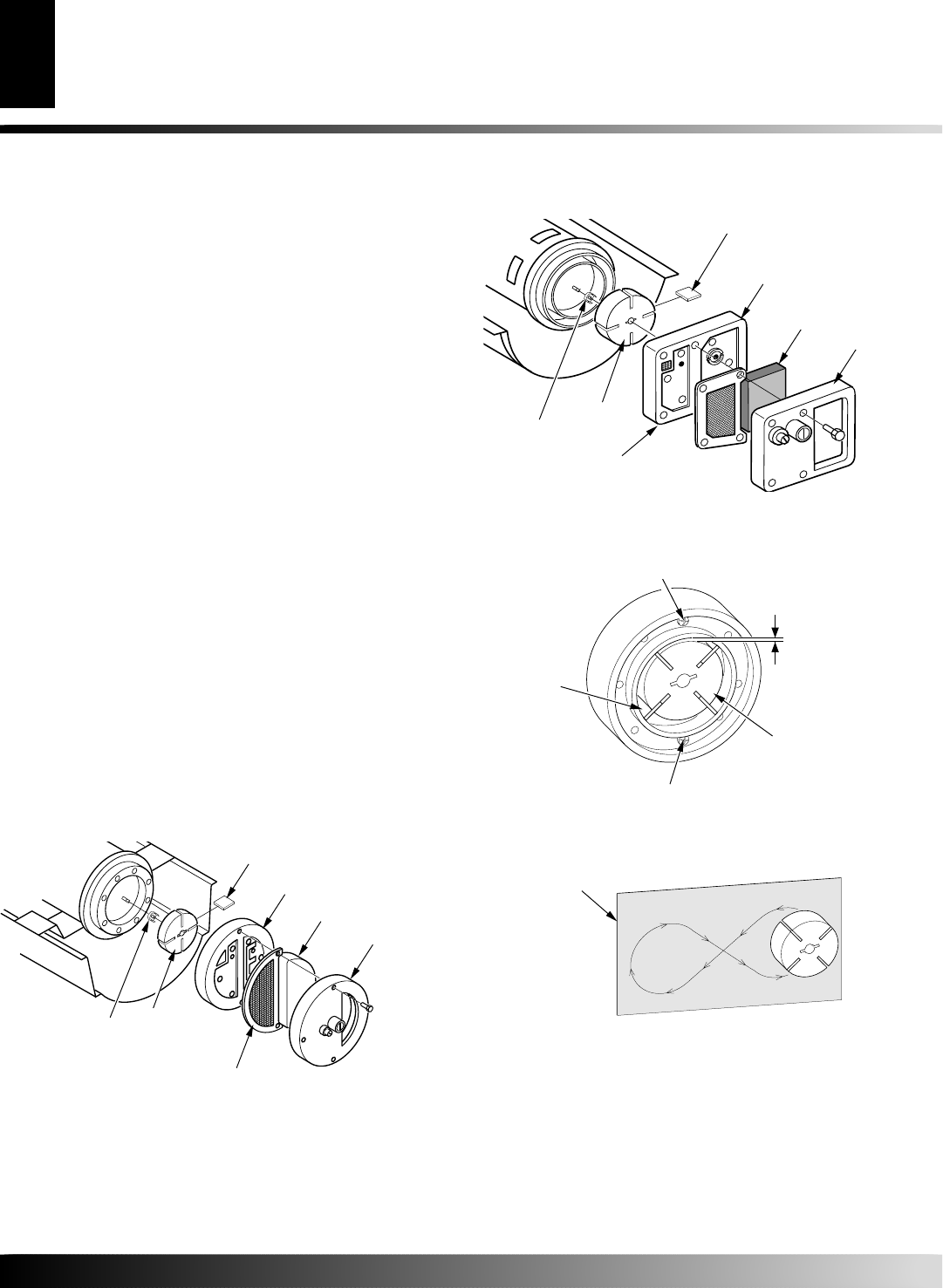
PUMP ROTOR
(Procedure if Rotor is Binding)
1. Remove upper shell (see Upper Shell Removal, page 8).
2. Remove filter end cover screws using 5/16" nut driver (see Fig-
ure 28 or 29).
3. Remove filter end cover and air filters.
4. Remove pump plate screws using 5/16" nut-driver.
5. Remove pump plate.
6. Remove rotor, insert, and blades (see Figure 28 or 29).
7. Check for debris in pump. If debris is found, blow out with
compressed air.
8. Install insert and rotor.
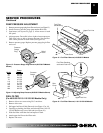
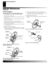
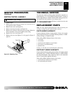
9. Check gap on rotor. Adjust to .076/.101 mm (.003"/.004") if
needed (see Figure 30).
Note:
Rotate rotor one full turn to ensure the gap is .076/.101 mm
(.003"/.004") at tightest position. Adjust if needed.
10. Install blades, pump plate, air filters, and filter end cover.
11. Replace fan guard and upper shell (see Upper Shell Removal,
page 8).
12. Adjust pump pressure (see Pump Pressure Adjustment, page 9).
Note:
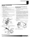
If rotor is still binding, proceed as follows.
13. Perform steps 1 through 6.
14. Place fine grade sandpaper (600 grit) on flat surface. Sand ro-
tor lightly in “figure 8” motion four times (see Figure 31).
15. Reinstall insert and rotor.
16. Perform steps 10 through 12.
SERVICE PROCEDURES
Continued
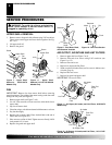
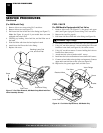
Figure 28 - Rotor Location, 40/55/60/70 Models
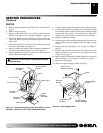
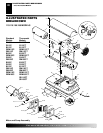
Figure 29 - Rotor Location, 110/115/155/165/200 Models
Insert
Blade
Rotor
Pump Plate
Air Intake
Filter
Air Output
Filter
Pump Plate
Insert
Rotor
Blade
Filter End
Cover
Air Intake Filter
Air Output
Filter
Filter End
Cover
Gap Adjusting Screw
Rotor
Blade
.003"/.004"
(.076-.101 mm)
Gap Measured
With Feeler
Gauge
Gap Adjusting Screw
Figure 30 - Gap Adjusting Screw Locations
Sandpaper
Figure 31 - Sanding Rotor
SERVICE PROCEDURES