


111167-01C
12
For more information, visit www.desatech.com
For more information, visit www.desatech.com
SERVICE PROCEDURES
Continued
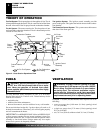
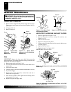
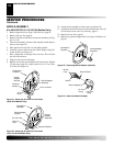
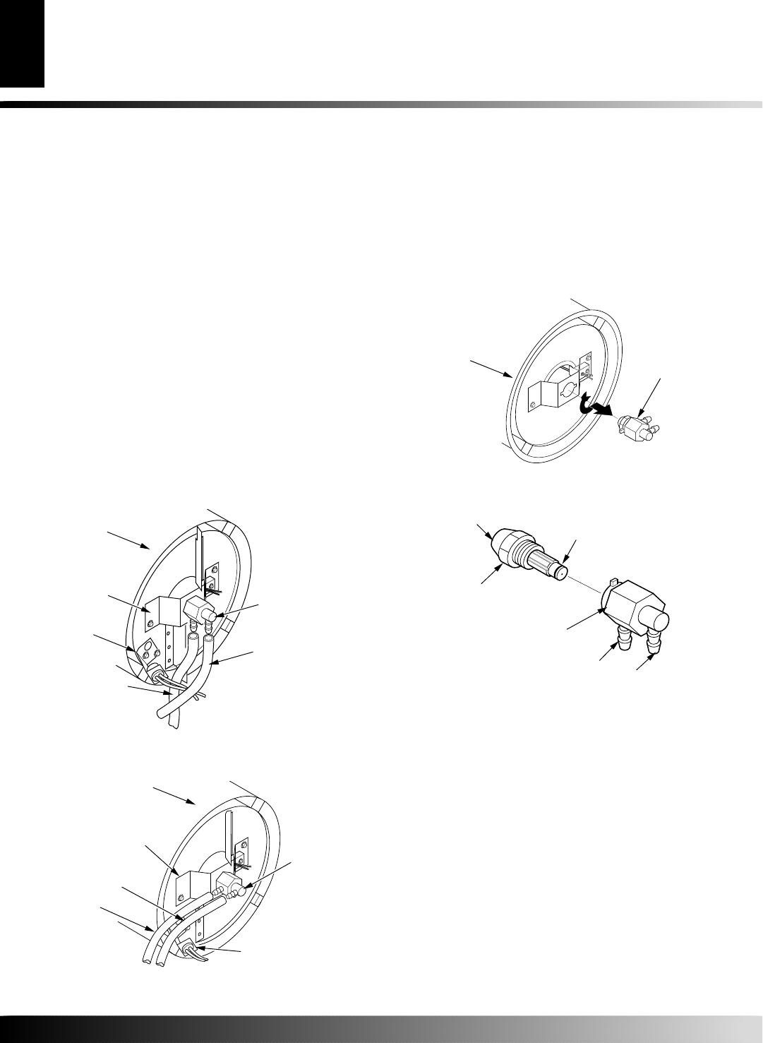
Figure 22 - Removing Air and Fuel Line Hoses
(110/115/155/165 Models Only)
NOZZLE ASSEMBLY
(For 40/55/60/70/110/115/155/165 Models Only)
1. Remove upper shell (see Upper Shell Removal, page 8).
2. Remove fan (see Fan, page 8).
3. Remove fuel and air line hoses from nozzle assembly (see Fig-
ure 21 or 22).
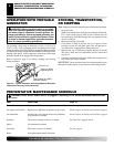
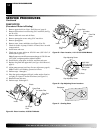
4. Turn nozzle assembly 1/4 turn to left and pull toward motor to
remove (see Figure 23).
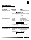
5. Place plastic hex-body into vise and lightly tighten.
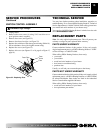
6. Carefully remove nozzle from the nozzle adapter using 5/8"
socket wrench (see Figure 24).
7. Blow compressed air through face of nozzle. This will free
any dirt in nozzle area.
8. Inspect nozzle sleeve for damage.
9. Replace nozzle into nozzle adapter until nozzle seats. Tighten
1/3 turn more using 5/8" socket wrench 4.5 to 5.1 N-m (40 to
45 in-lbs). See Figure 24.
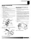
Fuel Line
Hose
Nozzle/
Adapter
Assembly
Combustion
Chamber
Air Line Hose
Photocell Bracket
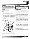
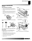
Figure 21 - Removing Air and Fuel Line Hoses
(40/55/60/70 Models Only)
Fuel Line Hose
Air Line
Hose
Nozzle Adapter
Bracket
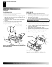
SERVICE PROCEDURES
Nozzle/Adapter
Assembly
Combustion
Chamber
Photocell
Bracket
Nozzle
Adapter
Bracket
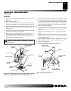
10. Attach nozzle assembly to burner strap (see Figure 23).
11. Attach fuel and airline hoses to nozzle assembly. See Fuel and
Airline Replacement and Proper Routing, page 13.
12. Replace fan (see Fan, page 8).
13. Replace fan guard and upper shell (see Upper Shell Removal,
page 8).
Figure 23 - Removing Nozzle/Adapter Assembly
Nozzle/Adapter
Assembly
Combustion
Chamber
Figure 24 - Nozzle and Nozzle Adapter
Nozzle
Face
Nozzle
Nozzle Sleeve
Nozzle Adapter
Air Line
Fitting
Fuel Line
Fitting