


111167-01C
11
11
For more information, visit www.desatech.com
For more information, visit www.desatech.com
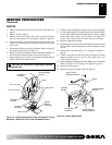
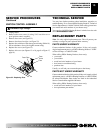
CAUTION: Do not bend or strike ignitor element.
Handle with care.
IGNITOR
1. Remove upper shell and fan guard (See Upper Shell Removal,
page 8).
2. Remove fan (see page 8).
3. Remove 4 side cover screws with a 5/16" nut driver. Remove
side cover (see Figures 15 or 16, page 9 or Figure 17, page 10).
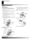
4. Disconnect ignitor wires from ignition control assembly (see
Figure 19). Pull the ignitor wires up through the hole in the
lower shell.
5. Disconnect fuel line hose and air line hose. Remove photocell
from photocell bracket (see Figure 19).
6. Remove combustion chamber. Stand combustion chamber on
end with nozzle adapter bracket on top (see Figure 20).
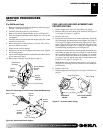
7. Remove ignitor screw with a 1/4" nut driver. Carefully remove
ignitor from nozzle adapter bracket.
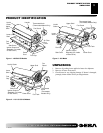
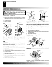
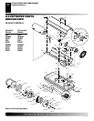
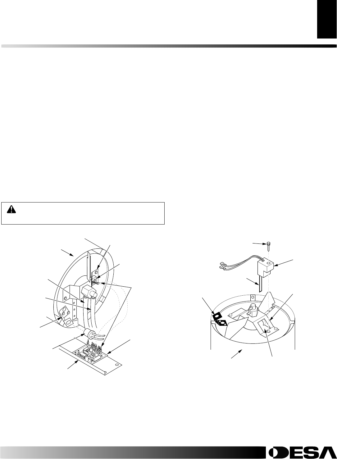
Figure 19 - Disconnecting Ignitor Wires from Ignition Control
Assembly (40/55/60/70/110/115/155/165 Models Shown)
Combustion
Chamber
Photocell
Bracket
Photocell
Assembly
Air Line Hose
Fuel Line Hose
Ignitor Wire
Ignitor
Nozzle Adapter
Bracket
Ignition
Control
Assembly
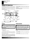
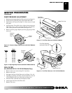
Side Cover
Photocell
Bracket
Ignitor
Ignitor Screw/
Washer Assembly
Nozzle Adapter
Bracket
Ignitor Element
Combustion
Chamber
Nozzle Adapter
Bracket Opening
Figure 20 - Ignitor Replacement
SERVICE PROCEDURES
Continued
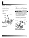
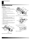
8. Carefully remove replacement ignitor from styrofoam packing.
9. Carefully guide ignitor into opening in nozzle adapter bracket.
Do not strike ignitor element. Attach ignitor to nozzle adapter
bracket with screw using a 1/4" nut driver (see Figure 20).
Torque .90 to 1.69 N-m (8 to 15 in-lbs) Do not over torque.
10. Replace combustion chamber.
11. Route the ignitor wires back down through the hole in the lower
shell. Connect wires to the ignition control assembly (see Fig-
ure 19).
12. Replace side cover (see Figures 15 or 16, page 9 or Figure 17,
page 9).
13. Connect and route fuel line hose and air line hose to nozzle
adapter assembly. See Fuel and Air Line Replacement and
Proper Routing, page 13.
14. Replace photocell in photocell bracket. Route wires as shown in
either (see Figures 21 or 22, page 12 or Figure 25, page 13).
15. Replace fan (see page 8).
16. Replace fan guard and upper shell (see page 8).
SERVICE PROCEDURES