


www.desatech.com
117437-01D12
WARNING: This appliance,
when installed must be electri-
cally grounded in accordance
with local code or in the ab-
sence of local code, with the
current National Electric Code,
ANSI/NFPA 70, or the Canadian
Electric Code, CSA C22.1.
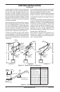
HIGH ALTITUDE INSTALLATION
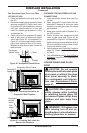
VENTING INSTALLATION
Continued
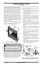
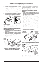
9-Volt
Alkaline
Battery
Receiver
Terminal
Wires
Battery Clip
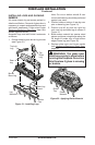
Figure 15 - Attaching Alkaline Battery to
Receiver
with local or provincial code authorities.
Consult your local gas company to help deter-
For assistance with any high altitude installa-
Service Department at 1-866-672-6040.
INSTALLING OPTIONAL CONTROLS
INSTALLING OPTIONAL WALL
MOUNT SWITCH - GWMS2
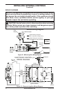
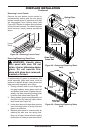
1. Connect one terminal of 15 foot wire from
wall switch to male connector on high limit
harness. Connect remaining wire terminal
to TH terminal on valve. Make sure that
wire terminals are in positions on unit as
pictured in Figure 14. If wires are not con-
nected as shown switch will not work.
2. Route 15 foot wire through hole openings
with bushings provided on either side of
3. Connect one bare wire end to each of
terminals of GWMS2 wall switch.
4. Install wall switch and cover in wall.
IMPORTANT: Do not use any other wire than
that provided with GWMS2 wall switch kit. Do
not exceed 15 feet of distance from valve con-
or exceeding minimum distance will increase
resistance at control valve causing unreliable
INSTALLING OPTIONAL WIRELESS
HAND-HELD REMOTE CONTROL
MODEL HRC100
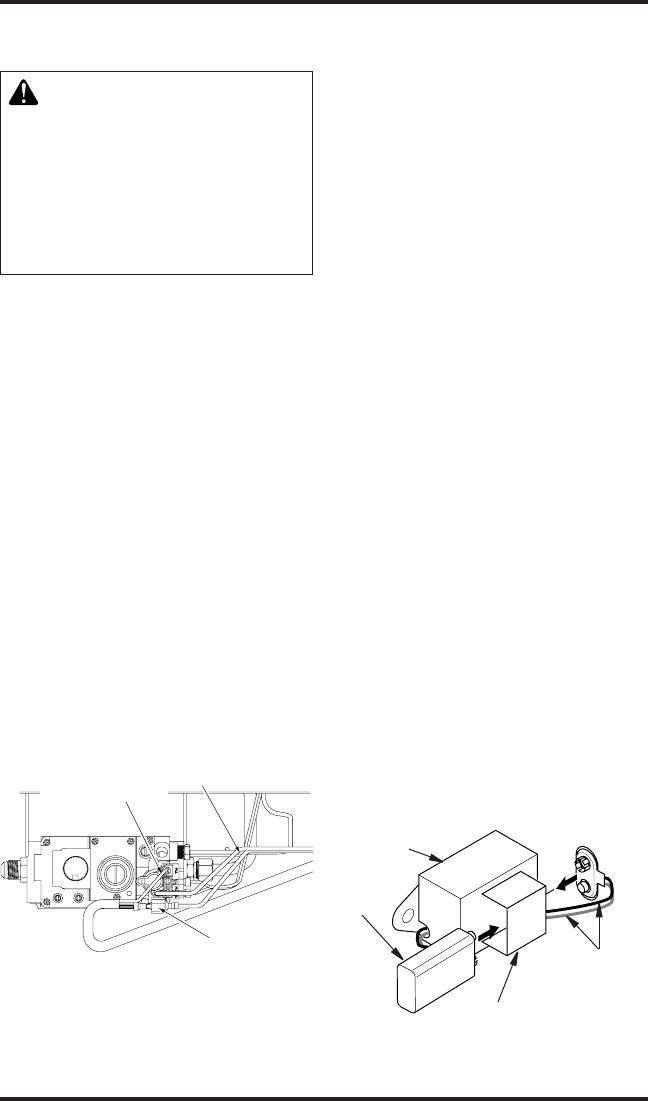
Installing Remote Receiver
1. Open bottom louver and locate switch
bracket on right side.
2. Locate battery clip mounted on back of
receiver. Slide a 9-volt alkaline battery
(not included) through clip.
3. Attach terminal wires to battery (see
Figure 15).
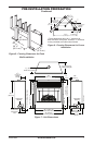
Remote Receiver
or Wall Switch to
Terminal Marked “TH”
Wire Harness From
High Limit Switch
Male Connector to
Remote Receiver
or Wall Switch
Figure 14 - Connecting Remote Receiver
or Wall Switch to the Gas Control Valve