


54
54
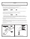
16) Set the fl ue collector onto the block and press down so that the fl ue collector is set into the silicone applied in the previous
step.
17) Slide the fl ue collector lugs back into position and retighten the ¼-20 bolts. DO NOT OVER TIGHTEN.
18) Apply a bead of silicone around the outside of the joint between the heat exchanger and the fl ue collector.
19) Reattach all the jacket components.
20) Reconnect the pressure switch tubes (see Figure 46 for correct tubing orientation).
21) Reconnect the fan.
22) Reconnect the vent system.
23) Reinstall the burner tray.
Service Notes
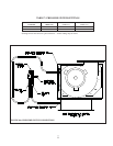
1) Orifi ce Size – Sea level orifi ce sizes are:
Natural Gas – #50 Drill Size
LP Gas – Consult Factory
Consult your Crown representative for correct orifi ce sizes for use at altitudes above 2000 ft. Orifi ce for this boiler cannot
be drilled in the fi eld.
2) Operating the Boiler with Intake Cover Removed – For inspection and troubleshooting purposes, this boiler may be started
and run with the intake cover removed. When this is done, a resonance (“hum”) may be observed. This is normal and
should disappear as soon as the intake cover is replaced.
WARNING
Do not leave the boiler in service with the intake cover removed.
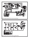
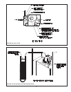
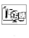
3) Pressure Switch – This boiler is equipped with a differential pressure switch which makes when there is adequate fl ue gas
fl ow through the boiler. This switch measures the pressure drop across an orifi ce plate inside the fl ue collector - the higher
the fl ue gas fl ow through this plate, the higher the pressure drop. The N.O. contacts on the pressure switch make, allowing
the boiler to fi re, when the pressure drop across the fl ue collector orifi ce plate switch exceeds the “make setting” shown in
Table 7. Once the switch is made, the boiler will fi re as long as the pressure at the switch is above the “break setting” shown
in Table 7. The pressure at both pressure switch tappings is actually below atmospheric (“negative”) with the pressure at the
upper fl ue collector tap being the more negative of the two pressures. Figure 46a shows the pressure switch connections.
Figure 46b shows the correct method of reading the pressure across the pressure switch tappings. It is normal for the
pressure reading across the switch to drop as the boiler heats up.
4) Burner and Pilot Removal - If necessary, the pilot can be removed without removing the burner tray. To do so, remove the
screws holding the main burners on each side of the pilot bracket. The main burners will then be loose enough to allow the
pilot hood to slip between them.
Main burners cannot be removed without removing the burner tray from the boiler.