


22
22
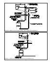
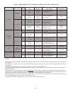
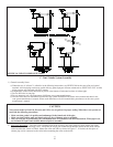
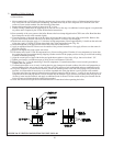
FIGURE 16: USE OF CONDENSATE TRAPS
C. Vent / Intake System Assembly
1) General Assembly Notes:
a) Where the use of “silicone” is called for in the following instructions, use GE RTV 106 for the vent collar and coaxial
terminal. Air inlet piping sections are sealed with any general-purpose silicone sealant such as GE RTV102. PVC air inlet
piping sections are connected with PVC cement.
b) Longitudinal welded seams should not be placed at the bottom of horizontal sections of exhaust pipe.
c) Do not drill holes in vent pipe.
d) Do not attempt to mix vent components of different vent system manufacturers.
e) In some cases, there are differences between the vent system installation instructions in this manual and those in the
vent system manufacturer’s manual. Where such differences exist, this manual takes precedence over the vent system
manufacturer’s manual.
CAUTION
Vent systems made by Heat Fab, Protech, and Z-Flex rely on gaskets for proper sealing. When these vent systems are
used, take the following precautions:
• Make sure that gasket is in position and undamaged in the female end of the pipe.
• Make sure that both the male and female pipes are free of damage prior to assembly.
• Only cut vent pipe as permitted by the vent manufacturer in accordance with their instructions. When pipe is cut,
cut end must be square and carefully deburred prior to assembly.
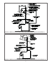
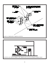
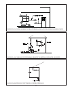
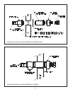
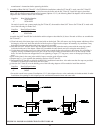
2) Vent Collar Installation – The vent collar is shipped loose in the accessory bag along with two collar gaskets, the outlet
orifi ce, and four 10-32 mounting screws. Verify that the 6 digit part number model number marked on the outlet exhaust
orifi ce matches that shown in Table 6. Mount the collar and orifi ce as shown in Figure 17. If desired, the fi rst piece of
exhaust pipe can be connected to the collar before mounting the collar on the boiler.