


9
9
VI Venting
WARNING
Failure to vent this boiler in accordance with these instructions could result in unreliable boiler
operation, severe damage to the boiler or property, or unsafe operation:
* Do not attampt to vent this boiler with galvanized, PVC, or any other vent system not listed in Table 4.
* Do not attempt to mix components from different approved vent systems.
* Do not install a barometric damper or drafthood on this boiler.
* Do not attempt to use the vent system for this boiler with any other appliance.
* Moisture and ice may form on the surfaces around the vent termination. To prevent deterioration,
surfaces should be in good repair (sealed, painted, etc.)
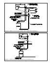
A. Vent System Design
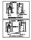
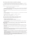
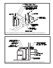
There are three basic ways to vent the CWD boiler:
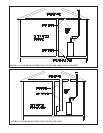
• Horizontal (“side wall”) Venting - Vent system exits the building through an outside wall. Combustion air is either
obtained through a separate pipe from outside (a “direct vent” installation) or obtained from the boiler room (a “direct
exhaust” installation).
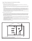
• Vertical Non-Coaxial Venting - Vent system exits the building through a roof. Combustion air is either obtained
through a separate pipe from outside (a “direct vent” installation) or obtained from the boiler room (a “direct exhaust”
installation).
• Vertical Coaxial Venting - Vent system exits the building through a roof. A portion of the vent system is coaxial, meaning
that it consists of a “pipe within a pipe”. Flue gasses exit the building through the inner pipe and combustion air is drawn
through the space between the two pipes.
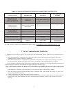
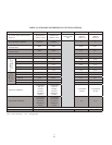
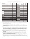
For each of the above three basic methods, there are several variations, resulting in a total of 13 options for venting
the CWD boiler. A description of each of these venting options is listed in Tables 3a - 3c. For clarity, these vent options are
numbered from 1 to 13 in Table 3. One of the vent option columns in Table 3 must match the planned vent and air intake
system exactly. In addition, observe the following guidelines:
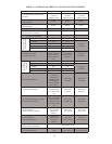
1) Approved vent systems - Use only one of the approved vent systems shown in Table 4. These systems are made of a special
stainless steel alloy (AL29-4C) for protection against corrosive fl ue gas condensate. They are also designed to provide a gas
tight seal at all joints and seams so that fl ue gas does not enter the building. Each approved vent system has unique method
for installation - do not attempt to mix components from different vent systems. The only exceptions are:
• Heat Fab Saf-T Vent SC may be combined with Saf-T Vent EZ Seal.
• Protech FasNSeal W2 may be combined with Protech FasNSeal.
See the vent installation section of this manual for information on how this can be done.
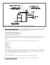
Heat Fab Saf-T Vent SC is a double wall vent system which can be used in two ways on CWD installations. In vertical
coaxial vent systems (Vent Options 12 and 13), the space between the inner and outer pipes is used as a conduit to bring
combustion air to the boiler. In Horizontal (Vent Options 1 to 5) and Vertical (Option 6 to 10) vent systems, Saf-T Vent SC
can be used to obtain a 0” clearance to combustible construction. When this is done, the space between the inner and outer
pipes is used for ventilation, but boiler combustion air comes from elsewhere.
Protech FasNSeal W2 is also a double wall vent system. In some cases, it can used to obtain closer clearances to
combustible construction than are possible using Protech FasNSeal (see Table 2). The space between the inner and outer
pipes on FasNSeal W2 cannot be used as a combustion air conduit.
The Crown Vertical coaxial vent system (Vent Option 11) is similar to that constructed using Heat Fab Saf-T Vent SC
except it is constructed by running one of the 3” single wall vent systems shown in Table 4 inside 5” type “B” vent. The
space between the 3” vent and the “B” vent forms a conduit to bring combustion air to the boiler. The advantage of this
system is that it can be constructed using any of the vent systems shown in Table 4 except for Heat Fab Saf-T Vent SC and
Protech FasNSeal W2. No turns are permitted in the coaxial section of this system.