


50
50
12) Check the manifold pressure and adjust if necessary. To do this, use the following procedure:
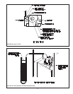
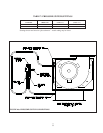
a) Connect a manometer to the line pressure tap on the gas valve (see Figure 44).
b) Check the line pressure with all gas appliances on and off. The line pressure at the boiler must be within the following
limits regardless of what combination of appliances is fi ring:
Line Press (inches w.c.) Natural Gas LP Gas
Minimum 5.0 11.0
Maximum 14.0 13.0
If the line pressure falls outside of these limits, fi nd and correct the cause of the problem before proceeding further.
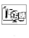
c) Disconnect the silicone regulator tube from the hose barb on the gas valve (Figure 45).
d) Connect a manometer to the manifold (outlet) pressure tap on the gas valve (Figure 44).
e) Read the manifold pressure. It should be set at:
Natural Gas LP Gas
Manifold Press. (inches w.c.) 3.5 10.0
e) If a manifold pressure adjustment is needed, make the adjustment by turning the regulator screw (see Figure 44)
clockwise to raise the pressure and counter-clockwise to reduce the pressure. If a manifold pressure adjustment is made,
recheck the line pressure to be certain that it is still within acceptable limits. Replace the cover screw on the regulator.
f) Reconnect the silicone regulator tube disconnected in Step (c)
13) Test thermostat operation while the boiler is running. Turn the thermostat to the lowest setting. Circulator should stop
running. Raise the thermostat back to the highest setting. Circulator should restart. The pilot burner and main burners
should relight.
14) Verify high limit operation. Allow the boiler water temperature to increase to high limit setting. Circulator should continue
running and pilot burner and main burners should stop fi ring. When water temperature drops below the limit setting, the
pilot burner and main burners should relight.
15) After the boiler has operated for approximately 30 minutes, check the boiler and heating system piping for leaks. Repair any
leaks found at once.
16) Inspect the vent system for fl ue gas leaks. Repair any leaks found before leaving the boiler in operation.
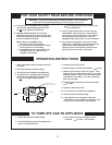
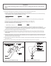
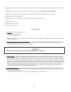
FIGURE 42: PILOT BURNER FLAME
FIGURE 43: MAIN BURNER FLAME
WARNING
Failure to follow the following procedure exactly could result in over-fi ring of the boiler and a carbon monoxide
hazard.