


44
44
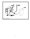
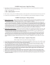
D. R8285 Control System - Single Zone Wiring
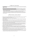
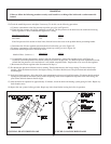
1) Line Voltage (120 VAC) Connections (Fig 37) – The line voltage connections are located in the junction box under the
R8285 fan center on the right side of the boiler.
• Black – Line voltage “hot”
• White – “Neutral” for boiler and circulators
• Green – Ground connection
2) The circulator is factory wired. If a different circulator is wired to the boiler, its full load current draw must not exceed 12A.
3) Connect the 24-volt thermostat to terminals “R” and “G” on the R8285 fan center. Set the heat anticipator to 0.34 Amps.
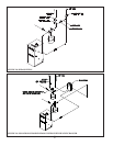
E. R8285 Control System - Wiring Variations
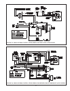
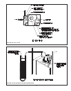
1) Multiple Circulator Zones – Figure 38 shows wiring for two or more circulator zones using Honeywell R845As. One fewer
R845A is used than the total number of circulator zones. A DPST Honeywell RA832A may be substituted in place of the
R845A using the “X” and “X” terminals in place of the “5” and “6” terminals on a R845A.
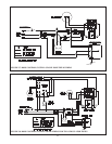
A call for heat from the “zone #1” thermostat causes the zone #1 circulator to start and the boiler to fi re exactly as in a
single zone system (see “Sequence of Operation”). A call for heat from any other thermostat will energize the DPST relay in
that zone’s R845A. When this relay is energized, electrical continuity is created between terminals 3 and 4, energizing the
circulator for that zone. At the same time, electrical continuity is created between terminals 5 and 6 on the R845A, creating
a current path from terminal “R” to “Y” on the R8285 fan center in the CWD. Assuming that the supply water temperature
is below the high limit setting, the normal ignition sequence will be initiated. If this happens when there is no call from the
zone #1 thermostat, the relay on the R8285A will not be energized and the zone #1 circulator will remain off.
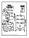
2) Multiple Zones using Zone Valves – Figure 39 shows wiring for multiple zones using Honeywell V8043F zone valves. This
wiring diagram may be used for other 24-volt zone valves as long as they are equipped with end switches. Do not attempt
to use the transformer on the R8285 to power the zone valves; use a separate transformer. Up to fi ve V8043Fs may be
powered by one 40VA transformer, such as the Honeywell AT87A.
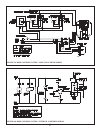
A call for heat from a given thermostat will result in the application of 24 volts across the TH and TR terminals on the
corresponding zone valve, energizing the zone valve motor. The zone valve opens and the end switch contacts are then
made. The end switches are connected in parallel with each other and to the CWD “thermostat” connections so that any
zone valve that opens will also start the circulator and fi re the boiler (assuming the high limit is not open). Zone valve
terminal TH/TR has no internal connection on the zone valve; it is merely a “binding post” used to connect two or more
wires.
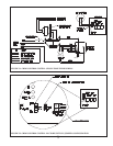
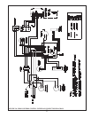
F. R8285 Control System – Sequence of Operation
(Refer to Figures 40 and 41 for ladder and connection diagrams)
1) A call for heat from the thermostat energizes relay coil 1K (the relay on the R8285), causing contacts 1K1 and 1K2 to make.
Contact 1K1 starts the circulator. Contact 1K2 sends power to the high limit.
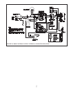
2) Assuming that the high limit is made, current will fl ow through the normally closed contacts on the pressure switch to relay
coil “2K” (the R8222 relay coil). Contacts 2K1 make, starting the combustion blower. Contacts 2K2 make, creating a
current path in parallel with the normally closed pressure switch contacts.
3) As the combustion fan comes up to full speed, the normally closed contacts on the vacuum switch break. Power remains
applied to the 2K coil, however, through the 2K2 contacts. Once the combustion fan has created adequate pressure across
the pressure switch, the normally open contacts on the pressure switch will make, sending power to the ignition module.
4) After 30 seconds has passed, the ignition module will initiate an ignition spark and apply 24 VAC across the pilot valve
(terminals “PV” and “MV/PV” on the gas valve).
5) If pilot fl ame is established before the 90 second trial for ignition period has ended, the spark will stop. Voltage is then
applied across the main valve (gas valve terminals “MV” and “MV/PV”) opening the valve and establishing main fl ame.
6) If no pilot fl ame is detected during the 90-second trial for ignition period, the pilot valve will close and the module will wait
30 seconds. It will then go through at least one more 90 second trial for ignition period, depending on the exact module
supplied with the boiler.