


38
38
IX Wiring
The CWD Series boiler is offered with two different types of control systems:
• CB502 Control System - Basic operation of the boiler is controlled with a “CB502 control” (Crown part #42-502) located
in the left side of the boiler vestibule. This device controls one or two circulator zones without the use of additional
controls and includes LEDs to show the status of the circulators, inducer, and other boiler controls.
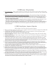
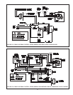
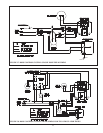
• R8285 Control System - Basic operation of the boiler is controlled by a Honeywell R8285 fan center. This system
controls a single zone, although it can be used in a multiple zone system through the use of additional controls. No
diagnostic LEDs are included in this system.
Both of these control systems use the same gas valves, ignition system components, and pressure switches.
Separate wiring instructions are provided for each of these two control systems in the following two sections.
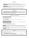
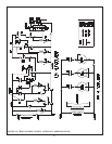
A. CB502 System - Single Zone Wiring
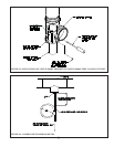
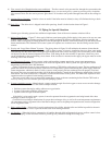
1) Line Voltage (120 VAC) Connections (Fig 31) – The line voltage connections are located in the junction box under the
transformer on the right side of the vestibule:
• Black – Line voltage “hot”
• White – “Neutral” for boiler and circulators
• Red – “Heating” circulator “hot”
• Blue – “Indirect Water Heater” circulator “hot” (This wire is not used in single zone installations)
• Green – Ground connection
2) Maximum circulator continuous current draw = 10A
3) Low Voltage (24 VAC) Connections (Fig 31) – These connections are screw terminals located on the front edge of the relay
board:
• T-T Heat 1 – “Heating” thermostat connections
• T-T DHW/H2 – “Indirect Water Heater” thermostat connections
• Heat anticipator setting for both thermostat connections is 0.03 A.
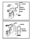
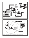
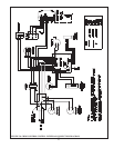
4) Priority Switch – When this switch is “on”, the “heating” circulator is turned off when a call for heat is present from
“indirect water heater” zone. It is used to ensure that the entire output of the boiler is available to the indirect water heater.
This switch should come from the factory in the “off” position and should be turned on only when absolutely necessary to
provide adequate domestic water.
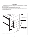
5) Auxiliary Jumpers – Two jumpers are located on the relay board as shown in Figure 32. They are present for connection and
confi guration of an auxiliary control. Unless instructions provided with the control call for these jumpers to be moved, they
should remain as shown in Figure 32.
WARNING
• All wiring and grounding must be done in accordance with the authority having jurisdiction or, in the absence of
such requirements, with the National Electrical Code (ANSI/NFPA 70).
• If a low water cut-off is installed, wire it to break the 120VAC supply to the boiler. Attempting to wire a 24 volt
low water cut-off into the boiler, or otherwise modifying any of the 24 volt boiler wiring, will void the ANSI Z21.13
certifi cation of this boiler and may cause unsafe boiler operation.
CAUTION
A problem with the indirect water heater zone could result in a total lack of heat and freeze damage to the building if
this switch is in the priority “on” position.
• Ensure that the priority switch is “off” when it is not to be used.
• Set the priority switch “on” only when absolutely necessary.
• Do not leave the priority switch “on” when the building will be empty for an extended period of time.