


40
40
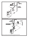
B. CB502 System - Wiring Variations
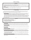
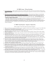
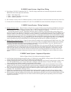
1) Two Circulator Zones – Figure 33 shows wiring for two circulator zones. The second zone may be either an indirect water
heater or a heating zone. No additional electrical controls are required to operate two circulator zones with a standard CWD
boiler.
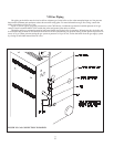
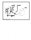
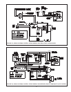
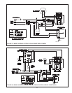
2) Hybrid Zone Valve/Circulator Zone System using Honeywell V8043Fs – The system shown in Figure 34 is useful when
zone valves are to be used for space heating zones but not the indirect water heater zone. Two circulators are wired into
the CWD boiler as shown in Figure 34. The zone valve end switches are connected in parallel and connected to the “T – T
Heat” thermostat connections. A separate transformer is required to power the zone valves – do not attempt to use the
transformer supplied with the boiler.
When a given heating thermostat calls, it opens the zone valve to which it is wired. When the zone valve opens, its end
switch makes, sending a call for heat to the CWD board. This starts the heating circulator and fi res the boiler.
The indirect water heater thermostat is connected directly to T-T DHW/H2. Upon a call for heat, it starts the indirect
water heater circulator and fi res the boiler. If the priority switch is “on”, a call from the indirect water thermostat also turns
off the heating circulator. CAUTION: Do not use the factory supplied transformer to power zone valves or other loads
external to the boiler.
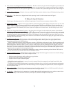
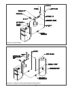
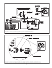
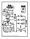
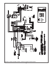
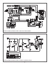
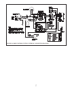
C. CB502 Control System – Sequence of Operation
(Refer to Figures 35 and 36 for ladder and connection diagrams)
1) When no call for heat is present and 120 VAC power is supplied to the boiler, the transformer is energized. The “PWR” LED
connected across the transformer secondary glows.
2) Assuming that no call for heat is present from the “DHW/H2” thermostat connections, a call for heat from the “Heat 1”
thermostat will apply voltage across relay coil 1K and the “Heat” LED.
3) When the 1K relay coil is energized, contacts 1K1 make, starting the heating circulator. Contacts 1K2 also make, sending
power to the high limit.
4) Assuming that the high limit is made, voltage will appear across the “Limit” LED which will illuminate, verifying that the
high limit switch is closed.
5) At this point, the pressure switch should be open and continuity should be present between the COM” and “N.C.” contacts
on the pressure switch. If this is the case, relay coil 3K will be energized along with the “FAN” LED. In the event that
the pressure switch is stuck in “fan proven” position at the beginning of the operating sequence, the “NC” contact on the
pressure switch will be open at this point and the operating sequence will not proceed further. This prevents the boiler from
fi ring if the pressure switch is stuck in the “fan proven” position.
6) Once relay coil 3K1 is energized, contacts 3K1 and 3K2 make. Contacts 3K1 energize the fan. Contacts 3K2 provide a
“latch” for coil 3K, ensuring that coil 3K remains energized after the pressure switch “normally closed” contacts open.
7) Once the combustion fan has created an adequate pressure differential across the pressure switch, the pressure switch “NO”
contacts will make. Voltage is then applied across both the “PRESS” LED and the ignition module.
8) After 30 seconds has passed, the ignition module will initiate an ignition spark and apply 24 VAC across the pilot valve
(terminals “PV” and “MV/PV” on the gas valve).
9) If pilot fl ame is established before the 90 second trial for ignition period has ended, the spark will stop. Voltage is then
applied across the main valve (gas valve terminals “MV” and “MV/PV”) opening the valve and establishing main fl ame.
10) If no pilot fl ame is detected during the 90-second trial for ignition period, the pilot valve will close and the module will wait
30 seconds. It will then go through at least one more 90 second trial for ignition period, depending on the exact module
supplied with the boiler.
11) A call for heat from the DHW/H2 thermostat will energize relay coil 2K and the “DHW” LED. Relay contacts 2K1 make,
starting the domestic water circulator. SPDT contacts 2K2 also change position, breaking one current path to relay coil 1K
and energizing the high limit. The boiler will then start following the sequence outlined in Steps (4) - (10).
12) The “priority switch “SW1” is “on” when it is open and “off” when it is closed. If the priority switch is “off”, a current path
will still exist to relay coil 1K after the 2K2 N.C. contacts have opened. If the priority switch is “on” (as shown in Figure
35), relay coil 1K will be de-energized, causing contacts 1K1 and 1K2 to open. The “heat” circulator will be de-energized,
but the burner will continue to fi re because the 2K2 “NO” contacts are made.