STEP 7 – COMPLETION OF MASONRY BRICK FRONT
The fireplace furnace front can be finished in many different ways to enhance the appearance of
your heating system. Ensure that all clearances have been met and that all insulation provided by
Country Flame has been installed correctly. Refer to local codes for any limitations of fireplace
fronts before completing the system. The following steps are provided as minimum requirements
in completing the fireplace furnace front installation.
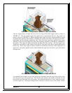
1. The fireplace face wall should be full masonry from floor to ceiling. An air space of at
least two inches must separate BOTH THE MASONRY AND THE MORTAR from the
front of the fireplace. Fill the two-inch void with the insulation provided by Country
Flame. No mortar should be closer than two inches from the fireplace front to allow for
heat expansion. Masonry may rest on the fireplace lintel and grille holder.
2. The fireplace mantle should be made of a non-combustible material. If combustible mantle
material is used, it must be placed at least twelve inches above the air outlet grille.
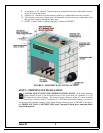
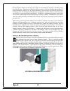
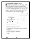
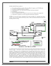
3. FIGURE 10 defines all the working components of the fireplace damper system. When
building the front masonry brick, be sure to
locate and mortar in the adjustable damper rod
sleeve, FIGURE 10, item (C).
4. The Smart Fireplace Furnace must be enclosed in a minimum of eight-inch thick masonry
material on both sides and the rear. This thickness is usually a combination of four-inch
thick concrete block and standard or common brick. Refer to STEP 4 – FIREPLACE
WALL CONSTRUCTION for review of this requirement.
5. A minimum of twenty-four inch sidewall clearance must be maintained between
combustibles and the interior firewall of the firebox.
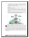
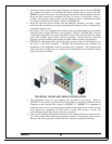
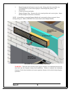
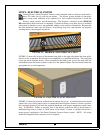
6. The fireplace heat grille and heat discharge boot come preinstalled from the factor and can
be used with any masonry brick up to 4” in thickness. If thicker masonry material is used,
refer to FIGURE 9B for a pictorial view of the assembly process of the optional adjustable
heat discharge boot. These optional parts are listed in the back of this manual. Order them
from your dealer.
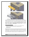
A. Mount “inner unit” (Part B, optional) to front of fireplace Part C using four (4) screws,
Part D.
B. Slide “outer unit” (Part A) onto “inner unit” (Part B, optional). If optional Part B has
not been purchased, mount Part A directly to Part C. Do not leave a gap between the
outer and inner units.
C. Adjust in and out for proper fit to brick facing.
D. The air discharge snap disc comes pre-installed and wired from the factory. Ensure
that it is wired to the home circuit by a certified electrician AND properly tested before
final face masonry is completed. A complete electrical circuit diagram is shown in
FIGURE 14.
E. Attach the grilles to the “outer unit” with the four screws provided.
7. Before completely enclosing the fireplace furnace unit, be sure the warm air ducts are
connected and installed in accordance with local building codes and constructed of material
capable of handling at least 250
0
F.
8. Maintain at least a four-inch clearance from the masonry chimney to combustibles below
the roofline or maintain a six-inch clearance from the factory built chimney to
combustibles below the roofline.
9. Use masonry or other non-combustibles to support the mantle.
Version 7.1
16


